Furman ASD-120 2.0 handleiding
Handleiding
Je bekijkt pagina 20 van 24
19
ASD-120 2.0 ACTIVATING MULTIPLE FURMAN MP-20 Q UNITS
ON
ASD-120 2.0 DIP SETTINGS
DLY
ADJ
1 2 3 4 5 6 7
ALWAYS ON
ALWAYS OFF
S
E
Q
SET TO
MIDDLE
POSITION
DELAY OUTPUTS
NC A B C D E F NO
12V STAT REM GND
FORCE
MP-20 Q #1 MP-20 Q #2 MP-20 Q #3 MP-20 Q #4 MP-20 Q #5 MP-20 Q #6
POSITIVE
TERMINALS
NEGATIVE
TERMINALS
M-8S WITH REMOTE SWITCH TRIGGERS ASD-120 2.0
ON
1 2 3
O
N
ASD-120 2.0 DIP SETTINGS
M-8S DIP SETTINGS
DLY
ADJ
1 2 3 4 5 6 7
ALWAYS ON
ALWAYS OFF
S
E
Q
SET TO
MIDDLE
POSITION
FORCE
RS-1 REMOTE SWITCH
12V STAT REM GND
12V STAT REM GND
M-8S REMOTE PORT
12V ON
12V OFF
GND
ON
MOM
MNT
DLY
ADJ
1 2 3
1
2
3
REMOTE PORT
12V STAT REM GND
DELAY 3
REMOTE PORT
12V STAT REM GND
AC RELAY ACCESSORY
MODEL PS-REL
C NO NC
PS-REL
PRIMARY M-8S UNIT
SECONDARY ASD-120 2.0
ASD-120 2.0
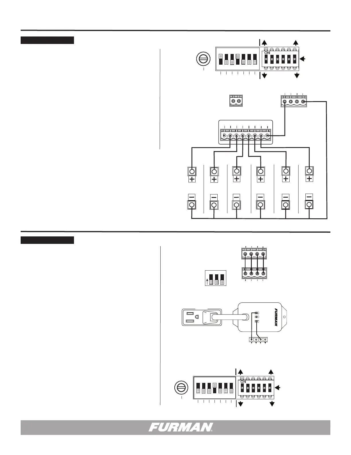
ASD-120 2.0 Sequencer Activates Multiple MP-20Qs via Bank DELAY OUTPUTS A through F.
Diagram #3 illustrates a Furman ASD-120 2.0 sequencer controlling six Furman MP-20Q units:
1. Connect REMOTE 12V terminal on ASD-120 2.0 to its own DELAY OUTPUT (NO)
terminal.
2. Connect MP-20Q negative (-) terminals to ASD-120 2.0 GND terminal on the
REMOTE interface.
3. Connect MP-20Q positive (+) terminals to ASD-120 2.0 DELAY OUTPUT contacts A
through F according to the desired match and timing for each MP-20Q.
4. Configure ASD-120 2.0 Multi-Function DIP for factory default, Maintained Mode ON.
• DIP 4 UP – (NO), verify factory default.
• DIP 7 DOWN – MNT, verify factory default.
• Ensure all Bypass Set DIP switches are SEQ.
• Configure ASD-120 2.0 Multi-Function DIP switches 1, 2 & 3 to the desired delay
time interval.
MP-20Q units will operate in sync with the ASD-120 2.0 Delay Banks A through F.
Diagram Example #4
A Furman M-8S Sequencer triggered by an optional RS-1 Remote System Control Panel
activates a Furman ASD-120 2.0 Sequencers at another in-house location.
Diagram #4 illustrates a Furman M-8S sequencer controlling an ASD-120 2.0 sequencer while
the optional RS-1 Remote System Control Panel act as the Primary Security Key Switch. This is
possible with the use of a Furman PS-REL AC Relay Accessory:
1. Configure ASD-120 2.0 Multi-Function DIP Set for Normally Closed & Maintained
Mode ON.
• DIP 1, 2 & 3 DOWN - ASD-120 2.0 Delay Time cannot exceed M-8S Delay Time.
• DIP 4 UP – (NO), verify factory default.
• DIP 7 DOWN – MNT, verify factory default.
• Configure ASD-120 2.0 Multi-Function DIP switches 1, 2 & 3 DOWN for short delay time.
• Ensure All Bypass Set DIP switches are selected as desired.
• Set ASD-120 2.0 Key Switch to Remote.
2. RS-1 terminals are connected to the M-8 S REMOTE terminals, pole to pole:
• 12V to 12V, REM to REM, STAT to STAT, and GND to GND.
3. Configure M-8S DIP Set or factory default, Maintained Mode ON.
• Configure M-8S DIP switches 1, 2 & 3 DOWN.
• Adjust Delay Interval to for a time longer than the ASD-120 2.0 Delay Interval.
• Plugged PS-REL into a M-8S Delay 3 Outlet.
• Connect PS-REL OUTPUT (NC) and (C) terminals to the ASD-120 2.0 12V and REM
terminals with a parallel connection: (NC) to 12V and (C) to REM.
• Flip the M-8S front panel switch to the ready Sequence On position.
When the M8-S is sequenced ON and its DELAY 3 outlet is energized, the PS-REL AC Relay
will trigger the ASD-120 2.0 to begin its programmed sequence.
Caution: The OFF sequence for the M-8S and ASD-120 2.0 will start at the same time.
In order to avoid timing conflicts while ramping down, set the M-8S to a longer delay time
than the total time interval on the ASD-120 2.0 sequencer.
DIAGRAM EXAMPLE 3
DIAGRAM EXAMPLE 4
Bekijk gratis de handleiding van Furman ASD-120 2.0, stel vragen en lees de antwoorden op veelvoorkomende problemen, of gebruik onze assistent om sneller informatie in de handleiding te vinden of uitleg te krijgen over specifieke functies.
Productinformatie
| Merk | Furman |
| Model | ASD-120 2.0 |
| Categorie | Niet gecategoriseerd |
| Taal | Nederlands |
| Grootte | 3501 MB |


