Handleiding
Je bekijkt pagina 17 van 24
En-17
(2) Number of subordinate units setting for outdoor unit
Set the number of subor-
dinate units connected to
1 refrigerant system.
Set only the primary unit.
SET3 Number of
connect-
able out-
door units
Remarks
3 4
OFF OFF 0
Primary unit only
(Factory setting)
OFF ON 1
1 subordinate unit con-
nected
ON OFF 2
2 subordinate unit con-
nected
ON ON 3
3 subordinate unit con-
nected
7.2.3 Terminal resistor setting
CAUTION
Be sure to set the terminal resistor according to specifications.
Set the terminal resistor for every network segment (NS).
If terminal resistor is set in multiple devices, the overall communication system may be
damaged.
If terminal resistor is not set in a device, abnormal communication may occur.
• Be sure to set 1 terminal resistor in a network segment. You can set the terminal resistor
at the outdoor unit or Signal amplifier.
• When setting the terminal resistor of a Signal amplifier, refer to the installation manual of
the Signal amplifier.
• When setting multiple terminal resistors, take note of the following items.
(1) How many network segments are there in a VRF system?
(2) Where will you set the terminal resistors in a network segment? (Condition for 1 seg-
ment: Total number of outdoor and indoor units and Signal amplifiers is less than 64,
or the total length of the transmission cable is less than 1,640 ft (500 m))
(3) How many outdoor units are connected to 1 refrigerant system?
Multiple outdoor unit setting
• The primary outdoor unit to the same refrigerant system subordinate outdoor unit.
(Transmission terminal H1, H2)
Number of outdoor units 1 2 3 4 (*2)
When use the UTY-SPWX (*1) —
— — —
SET5-1
Out door unit 1
(Primary)
Off On On Off On Off On
Out door unit 2
(Subordinate 1)
— — On On Off Off Off
Out door unit 3
(Subordinate 2)
— — — — On On Off
Out door unit 4
(Subordinate 3)
— — — — — — On
*1: Pressure sensor kit (indoor unit optional parts)
*2: When 4 outdoor units are connected, Pressure sensor kit cannot be available.
SET5-1
H1/H2
X1/X2
H1/H2
X1/X2
Y1/Y2
SET5-1
Setting example
Terminal resistor
setting (SET5-1)
(Primary)
(Primary)
UTY-SPWX (Pressure sensor kit)
4 outdoor units in a
refrigerant system
4 outdoor units with UTY-SPWX
in a refrigerant system
: Set to on : Set to off
System communication setting
• The primary outdoor unit to the indoor
units. (Transmission terminal X1, X2)
• The primary outdoor unit to the other
refrigerant system primary outdoor
unit. (Transmission terminal Z1, Z2)
SET5-4
Terminal
resistor
Remarks
Off Disable (Factory setting)
On Enable —
SET5-4
SET5-4
SET5-4
X1/X2
X1/X2
X1/X2X1/X2
Z1/Z2
Z1/Z2
H1/H2
H1/H2
H1/H2
Setting example
NS2 (Network
segment 2)
NS3 (Network
segment 3)
NS4 (Network
segment 4)
NS1 (Network segment 1)
(Primary)
(Primary)
(Primary)
Refrigerant system 1
Refrigerant system 2
Refrigerant system 3
*3: For all subordinate
outdoor units, set
SET5-4 to off.
Terminal resistor
setting
• Primary outdoor
unit (SET5-4) (*1)
Resistor
installed
Resistor not
installed
: Set to on
: Set to off
• Signal amplifier
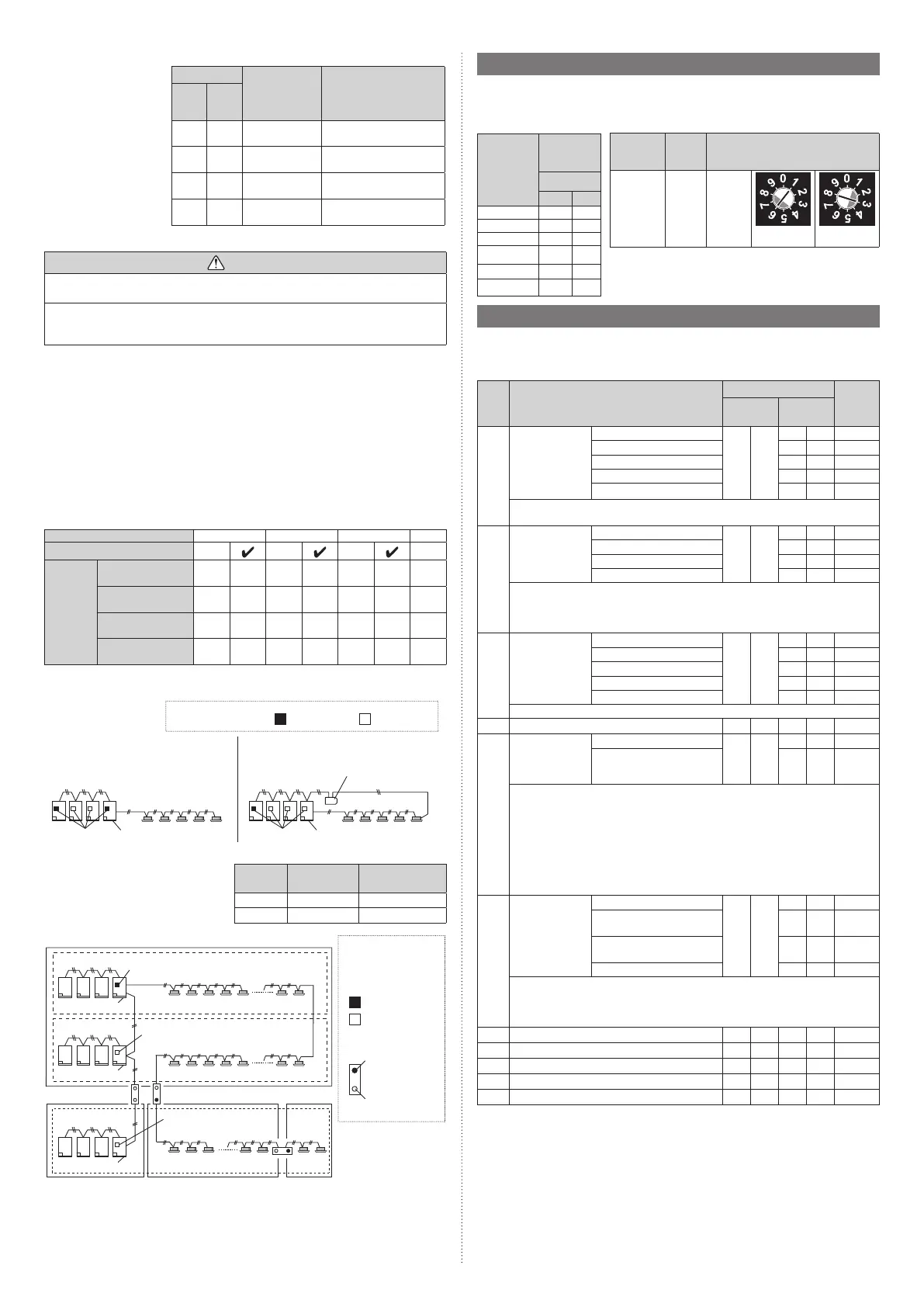
7.3. Rotary switch setting
The rotary switch (REF AD) sets the refrigerant system address of the outdoor unit. Con-
figure the settings only on the primary unit of a refrigerant system.
If multiple refrigerant systems are connected, set the rotary switch (REF AD) as shown in
the table below.
Refrigerant
system
address
Rotary
Switch
Setting
REF AD
×10 ×1
0 0 0
1 0 1
2 0 2
⁞ ⁞ ⁞
98 9 8
99 9 9
Setting
Setting
range
Type of switch
Refrigerant
system
address
0 to 99
Setting
example
63
REFAD×10
REFAD×1
RotarySwitch(REFAD×1):Factorysetting“0”
RotarySwitch(REFAD×10):Factorysetting“0”
7.4. Push button setting
Various functions can be set when necessary.
Perform settings after all indoor units have stopped operation.
List of Settings
No Setting Item
7-segment display
Factory
default
First 2
digits
Last 2
digits
00
Pipe length set-
ting (*1)
Standard (40 to 65 m)
0 0
0 0
Short (less than 40 m) 0 1
Medium (65 to 90 m) 0 2
Long 1 (90 to 120 m) 0 3
Long 2 (120 to 165 m) 0 4
Pipe length means the length between primary outdoor unit and the nearest
indoor unit.
10
Sequential start
shift (*1)
Normal
1 0
0 0
21 seconds delay 0 1
42 seconds delay 0 2
63 seconds delay 0 3
The start-up timing of outdoor unit (compressor) can be set up so that it can delay
several seconds.
This feature is useful when multiple number of outdoor units are installed and
turned on at the same time to limit the starting current.
11
Cooling capacity
shift (*1)
Normal mode
1 1
0 0
Save energy mode 0 1
High power mode 1 0 2
High power mode 2 0 3
Prohibited 0 4
Set this item when necessary.
15 Prohibited (Factory default) 1 5 0 0
20
Switching be-
tween batch stop
or emergency
stop (*1)
Batch stop
2 0
0 0
Emergency stop 0 1
Thismodeselectsthepatternofthestopfunctiontobeoperatedbytheexternal
input terminal (CN134).
• Batch stop: The stop of all indoor units connected to same refrigerant system
due to input signal coming from CN134.
• Emergency stop: When emergency stop is actuated, the indoor unit does not
accept the operation command from the remote controller. On the other hand,
when the emergency stop is released (no input from CN134), the air conditioner
does not return to the original operation until the indoor unit is turned on by the
remote controller.
24
High static pres-
sure mode
Standard
2 4
0 0
High static pressure 1
(equivalent to 30 Pa)
0 1
High static pressure 2
(equivalent to 82 Pa)
0 2
Prohibited 0 3
When installing a duct to the blow-off outlet of an outdoor unit, set the high static
pressure mode according to the static pressure of the duct to be installed.
Furthermore, use this setting if the air blow of an outdoor unit is poor, such as when
installed in a place with a low ceiling.
25 Prohibited (Factory default) 2 5 0 0
26 Prohibited (Factory default) 2 6 0 0
27 Prohibited (Factory default) 2 7 0 0
28 Prohibited (Factory default) 2 8 0 0
29 Prohibited (Factory default) 2 9 0 0
9378945746-02_IM_En_240404_2.indd 179378945746-02_IM_En_240404_2.indd 17 2024/04/04 16:26:092024/04/04 16:26:09
Bekijk gratis de handleiding van Fujitsu AJG090JATAH, stel vragen en lees de antwoorden op veelvoorkomende problemen, of gebruik onze assistent om sneller informatie in de handleiding te vinden of uitleg te krijgen over specifieke functies.
Productinformatie
| Merk | Fujitsu |
| Model | AJG090JATAH |
| Categorie | Airco |
| Taal | Nederlands |
| Grootte | 5576 MB |


