Frigidaire GMOS1266SS handleiding
Handleiding
Je bekijkt pagina 40 van 72
Instrucciones de instalación
B
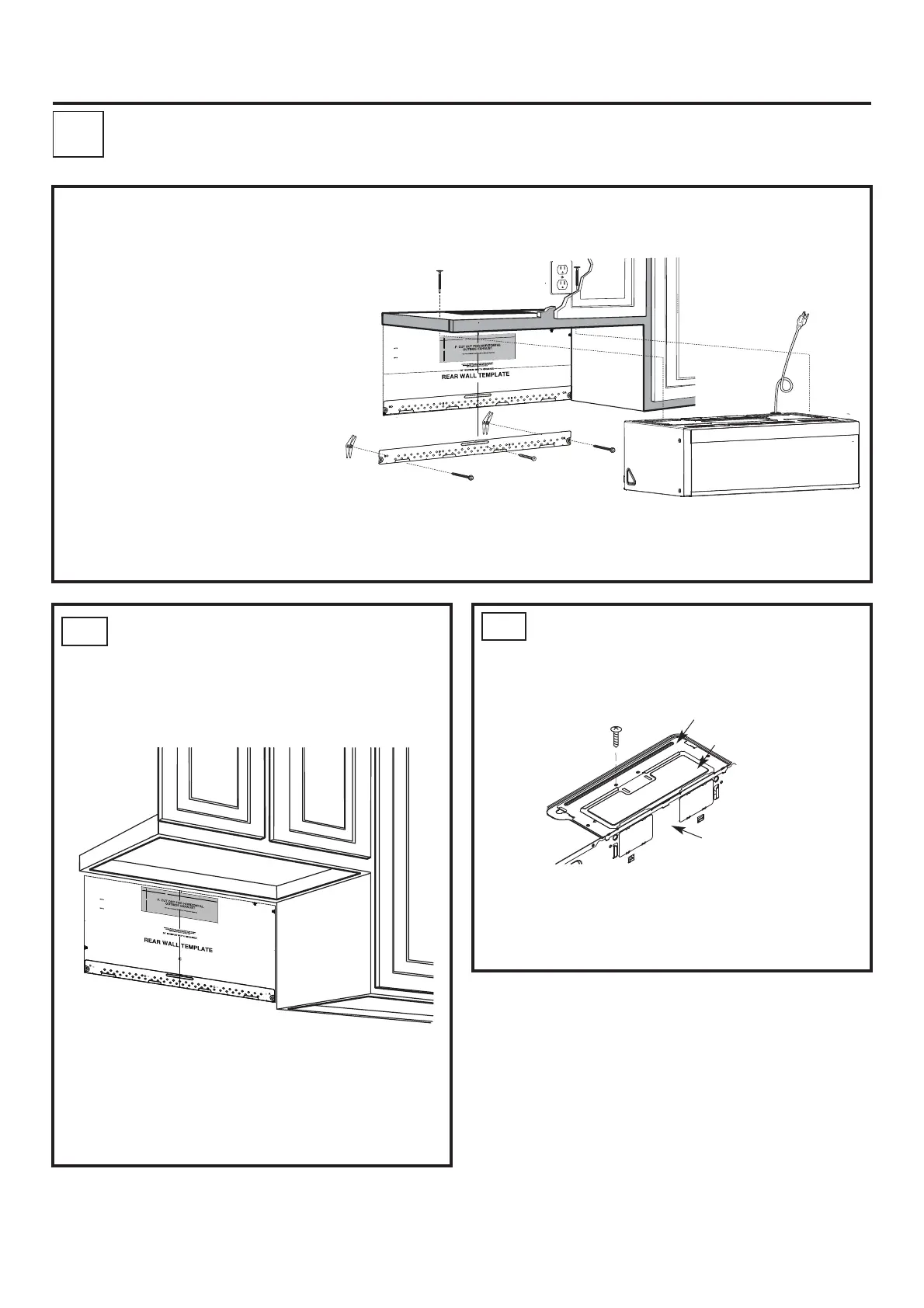
INSTALLATION OVERVIEW
NOTAS IMPORTANTES:
3/
8
"
TO
ED G
E
N
O
TE
:
IT IS
V
E
RY I
M
P
OR
TA
NT
T
O
REA
D
A
ND FO
LL
O
W
T
HE
D
I
RE
CT
IO
NS
I
N
THE
I
NST
A
LLA
T
I
O
N
I
NS
T
R
U
CT
ION
S
B
E
F
O
RE
P
R
O
CEE
DING
WITH T
H
IS
RE
A
R W
A
L
L
TE
MPL
A
TE
.
T
hi
s
R
e
a
r
Wa
ll
T
e
mp
l
a
t
e
serv
e
s
t
o
p
o
s
i
ti
o
n
th
e
b
otto
m
m
ou
n
ti
n
g
p
l
a
t
eand to l
o
ca
te
t
h
e
horiz
o
n
tal ex
hau
s
t
outl
e
t.
1
.
Us
e
a
le
ve
l
to
ch
ec
k t
h
at th
e
t
em
p
l
ate
is p
os
iti
on
ed
accu
r
at
el
y.
2. L
oca
t
e a
nd
m
ar
k a
t leas
t
on
estu
d
o
n the
l
ef
t or
r
ight si
de
o
f
the c
e
nt
e
rl
in
e
.
It
is
im
p
ort
an
t t
o
use
a
t
le
as
t o
ne
wood
s
cr
e
w m
o
u
nte
d
fi
rm
l
y i
n a
s
tud to supp
or
t t
h
e wei
g
h
t
ofth
e
micr
o
w
ave
.
M
ar
k t
wo
addit
ion
al, evenl
ysp
aced
l
o
c
ation
s
f
or
th
e
s
upp
l
i
ed
t
o
g
gle
bo
l
ts.
3.
D
r
i
ll
h
ole
s
i
n
th
e
m
ark
e
d
loca
t
i
o
n
s.W
he
r
e
there
i
s
a st
u
d,
dr
ill
a
3
/
1
6
"
h
o
le
f
or
woo
d sc
r
e
ws
.
For
h
o
le
s
t
ha
td
o
not
l
ine
u
p
w
ith
a
s
tu
d, d
r
il
l
5
/
8
"
ho
le
s fo
r
t
o
gg
le
bo
l
ts
.
DO NO
T I
NSTAL
L T
HE MO
UN
T
IN
G P
LAT
E
AT
T
HI
S
T
IM
E
.
4
.
R
e
m
ove
the
tem
p
la
te fr
o
h
tm
e
r
e
a
r
wall.
5.
R
e
v
i
e
h
t
w
e
I
n
st
a
ll
a
tion
I
nst
r
u
c
tion bo
o
k f
or
y
ou
r
in
sta
ll
at
i
o
n s
i
t
ua
t
i
on
.
Lo
cate a
n
d m
a
rk holes to
align
w
ith
h
o
le
s
i
n th
e
m
o
u
n
tin
g
pl
a
te.
IM
P
O
RT
ANT
:
LOC
A
T
E A
T
L
EA
ST
ON
E
STUD
O
N EITH
ER
S
ID
E
O
F
TH
E
C
ENT
E
R
LIN
E
.
M
AR
K
T
HE LO
C
A
TION
FO
R
2 ADDITIO
N
AL, EVENL
Y
S
PACE
D
T
OGG
LE
BO
L
TS
I
N THE
MOUNTING
PLA
T
E
A
R
EA
.
L
o
c
ate
a
nd
m
a
r
k
h
o
les
to
a
li
gn
w
it
h
ho
l
es i
n
the
.
e
t
a
l
p
g
n
i
t
nu
om
IM
P
OR
T
A
N
T
:
L
OCA
T
E
AT
L
E
A
S
T
ON
EST
U
D
O
N EITHE
R
S
I
D
E
OF
T
HE
C
E
NT
E
R
L
I
N
E.
M
A
RK
T
HE
L
O
CAT
IO
N
FOR
2
A
DD
ITI
O
N
A
L
, EV
E
NL
Y
SP
A
CE
D
TO
GGLE
B
OLT
S
IN
T
H
E
M
OUNTIN
G
P
LA
T
E
AR
EA.
Trim
t
he
r
e
a
r
w
a
ll t
e
m
pl
a
te
a
l
on
g
th
e
d
o
tt
e
d li
n
e
.
Trim
t
he r
e
ar
wal
l t
e
mplat
e
a
long
t
he
d
ot
t
e
d
li
n
e
.
12"
4"
Dar
l
e
vue
l
t
a
a
l
ap
a
jo
ha
ra
con
s
u
l
t
ar
l
a
v
e
r
si
ó
n
e
n
Esp
a
ñ
ol.
B1.
3
/8" TO E
D
GE
NO
TE
: IT IS VE
RY IM
POR
T
ANT
TO
R
E
AD
A
ND
FOLL
OW
TH
E
DIR
ECTIONS
IN T
HE INSTA
L
LATIO
N
INSTR
U
CTIO
NS
BEFO
RE
PROCEEDING
WITH
THI
S
RE
AR
WALL
TEMPLATE
.
Th
is
Rear
W
all
Te
m
pl
at
e s
er
v
es
t
o
p
osit
i
on
t
h
e bot
t
om
m
ount
in
g
pl
a
te
a
nd
t
o
lo
c
a
t
e
t
he
hori
z
o
ntal
exhaust
ou
t
let
.
1.
Us
e
a
le
vel
t
o check
that
t
h
e
t
e
m
pla
t
e
is
positione
d
accurat
ely.
2.
Locat
e
and
mark
a
t
lea
s
t
on
e
st
ud
on the
l
ef
t
or
right
side
o
f
t
h
e
ce
nt
erl
ine.
It
is
im
portant t
o
u
se at
leas
t
on
e wood
scr
ew
mou
n
t
e
d
f
irmly
in
a
st
ud
t
o
s
up
port
t
he
wei
ght
of
th
e
microw
ave.
Mar
k
t
wo a
ddition
al,
ev
enly
spa
ced
loca
ti
on
s
f
or
t
h
e
s
uppl
ied
t
ogg
le
bolt
s.
3.
Dr
ill
h
oles
in
t
h
e
m
arked loca
t
io
ns.
Wh
ere
t
h
er
e
i
s
a st
ud,
dri
ll
a
3
/
1
6"
ho
le
f
or wood
screws. F
o
r
holes
t
hat
do
n
ot li
ne
up
with
a stud,
drill
5
/
8
"
hole
s
f
or
t
oggle
b
olts
.
D
O
NOT
IN
S
T
ALL
T
HE
MO
UN
T
I
NG
P
LAT
E
AT
T
HI
S
T
I
M
E.
4.
Rem
o
ve
the
t
emplat
e
from
the
rear
wall.
5.
R
eview
th
e I
nstal
la
t
io
n
In
s
tr
uc
t
ion
bo
o
k
f
or
y
our
in
stallat
io
n
situat
io
n.
Lo
cate
and
mark hol
es to
alig
n with holes
in the
mou
nti
ng p
late
.
IMP
O
RTA
NT:
LOCATE
AT LE
AST ON
E
STU
D
O
N
EITH
ER
S
ID
E
O
F
TH
E
C
ENTER
LIN
E
.
M
A
R
K TH
E L
OC
AT
ION FOR
2 AD
D
IT
I
O
NAL,
EVENLY
SP
ACE
D TOGG
LE BO
LTS IN
TH
E
MOUNTIN
G
PLA
TE
AREA.
Lo
cate
and
mar
k holes to
a
lign w
ith h
o
les in the
mo
unti
ng
p
late
.
IMPORTA
NT:
LO
CAT
E
AT LE
AST ON
E
STU
D O
N EIT
H
ER SIDE
O
F
TH
E CE
N
TER
LIN
E.
MA
RK TH
E
L
OCAT
IO
N FOR
2 AD
DIT
IO
NAL
, EVEN
LY
SP
ACE
D TOGG
LE
BOLTS
IN
THE
M
OU
NTIN
G PLATE
AR
EA.
Trim the
r
ea
r wa
ll templa
te a
l
o
n
g the d
otted
line.
Tri
m
the
rea
r
wal
l
te
mpla
te
a
l
o
ng
the
d
otted
lin
e
.
12"
4"
Darle
vu
elta
a
la
ho
ja
pa
r
a
co
n
sul
tar
la
ver
sión
en
Espa
ñ
ol.
B2.
Placa del soplador
Placa de cubierta
ES-15
EXTRACCIÓN TRASERA EXTERNA (Conducto
Horizontal)
B1. Preparación de la pared trasera
B2. Desinstalación del placa del ventilador
B3. Montaje de la placa de instalación en
la pared
B4. Preparación del gabinete superior
B5. Ajuste del ventilador
B6. Instalación del horno microondas
• Asegúrese de que los tornillos del
motor del ventilador y la placa del
ventilador queden firmemente
apretados al volver a instalarlos.
Esto ayudará a prevenir el exceso de
vibraciones.
• Asegúrese de que el cableado del
motor quede debidamente orientado y
asegurado, y que los cables no queden
atrapados.
• Lea las instrucciones de la sección PLANTILLA
PARA LA PARED TRASERA.
• Adhiera con cinta la plantilla a la pared trasera.
• Realice el corte de la abertura, siguiendo las
instrucciones de
la sección PLANTILLA PARA LA PARED TRASERA.
PREPARACIÓN DE LA PARED
TRASERA PARA LA SALIDA
DE EXTRACCIÓN TRASERA
Es necesario realizar un corte en la pared trasera
para crear una
abertura para la salida de extracción externa.
QUITAR LA PLACA DEL
SOPLADOR
Retire y guarde el tornillo que sujeta la placa
del soplador al microondas. Levante la placa
del soplador.
• La placa de cubierta se instala con la placa
del soplador, no es necesario separarla.
Parte trasera del
microondas
Bekijk gratis de handleiding van Frigidaire GMOS1266SS, stel vragen en lees de antwoorden op veelvoorkomende problemen, of gebruik onze assistent om sneller informatie in de handleiding te vinden of uitleg te krijgen over specifieke functies.
Productinformatie
| Merk | Frigidaire |
| Model | GMOS1266SS |
| Categorie | Magnetron |
| Taal | Nederlands |
| Grootte | 11447 MB |


