Handleiding
Je bekijkt pagina 27 van 37
27
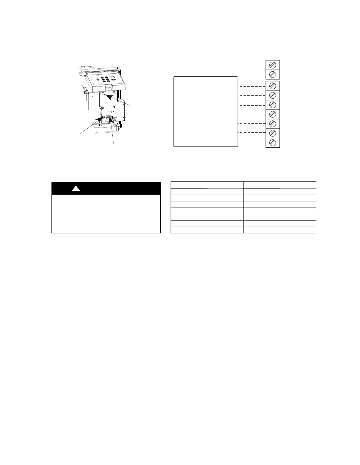
F. REMOTE THERMOSTATS
F.2 Terminal Connections
TERMINAL CONNECTIONS
The wall thermostat terminal block is located behind the front panel and is easily accessible on front
of control panel.
R
Y
GH
GL
C
W
O
Common
(24VAC in)
TYPICAL WALL THERMOSTAT
TERMINAL BLOCK
See Note 1
See Note 2
Energy
Management
NOTES:
1.Use terminal“O” for heat pump unit connection only.
2.Terminal“C”(common) is typically only required for digital thermostats.
TERMINAL DESIGNATION
R 24VAC
W Electric Heat
Y Compressor
O Reve
r
sing Valve
GH High Fan
GL Low Fan
C Common
Fig. F.2.1 –Terminal Connector and Status LED Location
UNIT DAMAGE HAZARD
CAUTION
!
Failure to follow this caution may result in equipment
damage or improper operation.
Improper wiring may damage unit electronics.
Common busing is not permitted.Damage or erratic
operation may result.
ENERGY MANAGEMENT INPUT (FRONT DESK CONTROL)
The controller can handle a switch signal from remote energy management input, called EM signal or
front desk control. Input must be 24VAC. If system receives a 24VAC signal,it will turn unit off; otherwise,
the unit runs in normal control.This function will be disabled under Freeze Guard protection. See Fig. F.2.1
and Fig. F.2.2 for terminal connections.
NOTE: Any errant input combinations will be captured as thermostat wiring
failures and will light the STATUS LED indicator on main board
(see Intelligent Self---Checking Control section).
STATUS
LED
Wall Thermostat
Terminal Connections
Energy Management
Terminal Connections
Fig. F.2.2
J. STARTUP AND OPERATION
J.1 Final Inspection
• Inspect and ensure that all components and accessories have
been installed properly and that they have not been damaged
during the installation progress.
• Check the condensate water drain(s) to ensure that they are
adequate for the removal of condensate water, and that they
meet the approval of the end user.
• Ensure that all installation instructions concerning clearances
around the unit have been adhered to. Check to ensure that
the unit air filter, indoor coil, and outdoor coil are free from any
obstructions.
• Inspect the unit for any damage to the coils and tubing that could
cause a leak.
• Ensure that the circuit breaker(s) or fuse(s) and supply circuit
wire size have been sized correctly. If the unit was supplied with
a power supply cord, insure that it is stored properly.
• Ensure that the entire installation is in compliance with all
applicable national and local codes and ordinances having
jurisdiction.
• Secure components and accessories, such as a decorative front
cover.
• Start the unit and check for proper operation of all components in
each mode of operation.
• Instruct the owner or operator of the units operation, and the
manufacturer’s Routine Maintenance.
NOTE: A log for recording the dates of maintenance and/ or service
is recommended.
Present the owner or operator of the equipment with the
Installation & Operation Manual, all accessory installation
instructions, and the name, address, and telephone number of the
Authorized Friedrich Warranty Service Company in the area for
future reference if necessary. Inspect the unit for any damage to
the coils and tubing that could cause a leak.
Bekijk gratis de handleiding van Friedrich ZoneAire Select PZH07K3SB, stel vragen en lees de antwoorden op veelvoorkomende problemen, of gebruik onze assistent om sneller informatie in de handleiding te vinden of uitleg te krijgen over specifieke functies.
Productinformatie
| Merk | Friedrich |
| Model | ZoneAire Select PZH07K3SB |
| Categorie | Airco |
| Taal | Nederlands |
| Grootte | 6056 MB |


