Handleiding
Je bekijkt pagina 26 van 37
26
F. REMOTE THERMOSTATS
F.1 Install Thermostat
All PZ model PTAC units are factory configured to be controlled by eitherthe
chassis mounted Smart Center or a 24v remote wall mounted thermostat.
The thermostat may be auto or manual changeover as long as the control
configuration matches that of the PTAC unit.
ALL PDH Models require a single stage cool, dual stage thermostat
with an O reversing valve control. The Freidrich RT6 thermostat is
applicable.
Install thermostat Approximately 5 ft. from the floor.
Install thermostat close to or in a frequently used room, preferably on
an inside wall.
The Thermostat should NOT be mounted:
Close to a window, on an outside wall, or next to a door leading outside.
Where it can be exposed to direct sunlight or heat, such as the sun,
a lamp, fireplace, or any ther temperatureradiating object which may
cause a false reading.
Close to or in the direct airflow of supply registers and/or return air
grilles.
Any areas with poor air circulation, such as a corner, behind a door, or
an alcove.
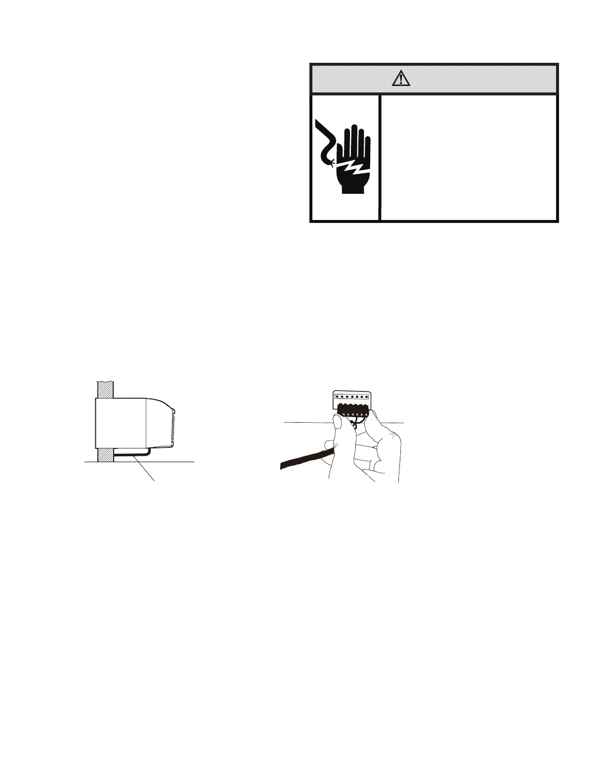
WARNING
Electrical Shock Hazard
Make sure your electrical receptacle has the
same configuration as your air conditioner’s
plug. If different, consult a Licensed Electrician.
Do not use plug adapters.
Do not use an extension cord.
Do not remove ground prong.
Always plug into a grounded 3 prong oulet.
Failure to follow these instructions can result in
death, fire, or electrical shock.
WALL THERMOSTAT TERMINAL
IMPORTANT: Only trained,qualified personnel should access electrical panel on unit and install
electrical accessories.Please contact your local electrical contractor,dealer,or distributor for
assistance.
Thermostat Wire Routing
Thermostat wire is field supplied.Recommended wire gauge is 18 to 20 gauge solid thermostat wire.
NOTE: It is recommended that extra wires are run to unit in case any are damaged during installation.
Thermostat wire should always be routed around or under, NEVER through,the wall sleeve. The wire
should then be routed behind the front panel to the easily accessible terminal connector.
THERMOSTAT WIRE ROUTING
(UNDER SLEEVE, BEHIND FRONT PANEL)
R W Y O Gh Gl C
Fig. F.1.1 –Proper Wire Routing Beneath Unit
Fig. F.1.2–Terminal Connector Removal and Replacement
Wiring Thermostat To Unit
Wire wall thermostat input as defined in Fig. F.2.2
NOTE: Terminal connector can be removed and replaced to simplify the wiring.
NOTE: For heat pump models,anytime there is a second-stage call for heating from the wall thermostat,
the unit will automatically switch over to electric heating.
Install Thermostat Wiring
2. Pull terminal connector to remove
NOTE:Terminal connector can be removed and replaced to simplify thermostat wiring.
3. Connect wires from the thermostat to terminals on unit terminal connector.
4. Reinstall terminal connector.
5. Ensure that unit is cofigured for wall thermostat enable.
6. Replace control panel label with wall thermostat label(included).
7. Restore power to unit.
NOTE: Refer to thermostat installation instructions for details on installing wall thermostat.
NOTE: For thermostats that have only one fan speed output (on or auto), the fan speed is determined
by how the terminal connector is wired. If Low fan is desired, wire the G output from the thermostat to
GL on the unit’s terminal block. If Hi fan is desired, wire the G output from the thermostat to GH on the
unit’s terminal block.
NOTE: After proper installation, if your thermostat is not working properly, refer to the Trouble Shooting
section.
14
1. Ensure that power is disconnected.
NOTE: Refer to Table J.3.3 (Dip Switch Functions) to set the thermostat mode.
Bekijk gratis de handleiding van Friedrich ZoneAire Select PZH07K3SB, stel vragen en lees de antwoorden op veelvoorkomende problemen, of gebruik onze assistent om sneller informatie in de handleiding te vinden of uitleg te krijgen over specifieke functies.
Productinformatie
| Merk | Friedrich |
| Model | ZoneAire Select PZH07K3SB |
| Categorie | Airco |
| Taal | Nederlands |
| Grootte | 6056 MB |


