Festo ELGS-BS-KF-32-500-8P-ST-M-H1-PLK-AA handleiding
Handleiding
Je bekijkt pagina 8 van 28
8
Festo — ELGS-BS — 2023-11e
Installation
2. Connect the logic cable to the [Logic] connection of the integrated drive EMCS-ST and to a
controller or to a IO-Link master.
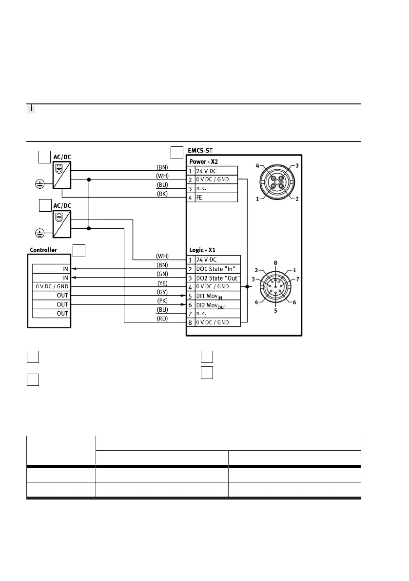
Wiring diagram: DIO operation (digital I/O)
In NPN mode defined levels must be applied to the DI1/DI2 digital inputs of the EMCS, e.g.by
controller outputs with pull-up resistors (4.3kW recommended).
1
2
3
4
Fig. 5: Wiring diagram: DIO operation (digital I/O)
1
PELV fixed power supply for the load
voltage supply
2
PELV fixed power supply for the logic power
supply
3
Integrated drive EMCS-ST
4
Higher-order controller with digital I/O
Status and control signals
The following table shows the status and control signals and the electrical levels of the digital inputs
and outputs as a function of the "PNP/NPN" version of the integrated drive.
Status and control
signal
Electrical levels
PNP, positive logic NPN, negative logic
0 Low level (0V) High level (24V)
1 High level (24V) Low level (0V)
Tab. 2: Overview of status and control signals as a function of electrical levels
Bekijk gratis de handleiding van Festo ELGS-BS-KF-32-500-8P-ST-M-H1-PLK-AA, stel vragen en lees de antwoorden op veelvoorkomende problemen, of gebruik onze assistent om sneller informatie in de handleiding te vinden of uitleg te krijgen over specifieke functies.
Productinformatie
| Merk | Festo |
| Model | ELGS-BS-KF-32-500-8P-ST-M-H1-PLK-AA |
| Categorie | Niet gecategoriseerd |
| Taal | Nederlands |
| Grootte | 2549 MB |


