Ferroli TP3 COND 65÷1000 handleiding
Handleiding
Je bekijkt pagina 66 van 92
66
EN
TP3 COND
cod. 3541T740 - Rev 05 - 08/2022
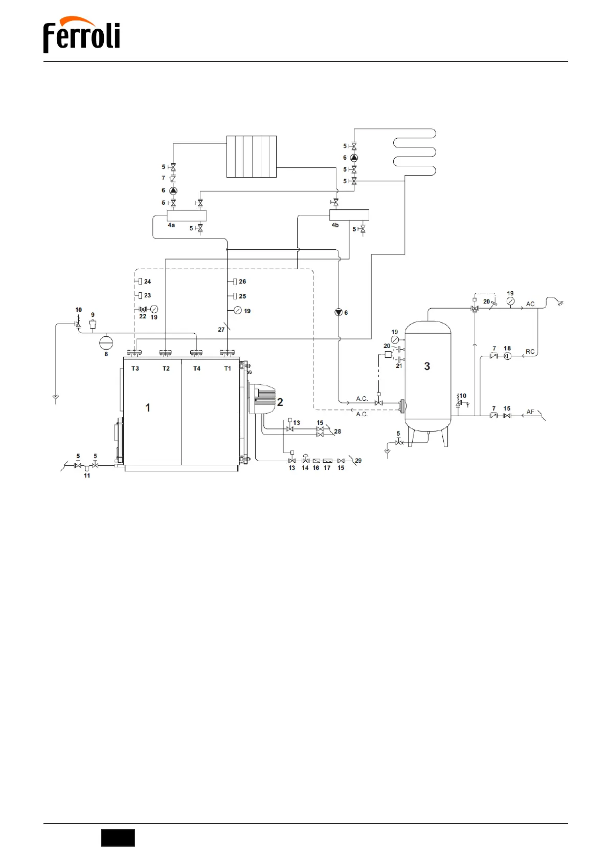
6. SCHEMATIC DIAGRAM - SYSTEM FOR HEATING AND DOMESTIC HOT WATER
The choice and installation of the system components is up to the installer, who must operate according to good practice and the current
Legislation. Systems with antifreeze require the use of backflow preventers. Remember that the diagram in fig. 19 is a schematic diagram.
In case of different systems, please contact our After-Sales Service which will provide all the elements you require.
fig. 19
Legend
T1 Heating delivery
T2 High temperature return
T3 Low temperature return
T4 Expansion vessel connection
1 Heat generator
2 Burner complete with shutoff and control valves
3 Hot water tank
4 System manifolds
5 Disconnecting valves
6 Circulating pump
7 Non-return valves
8 System expansion vessel
9 Automatic vent valve
10 Safety valve
11 Softener filter
12 System loading
13 Fuel shutoff valve
14 Gas pressure stabilizer
15 Manual shutoff valve
16 Gas filter
17 Vibration-damping coupling
18 Pump
19 Pressure gauge
20 Safety thermostat
21 Control thermostat
22 3-way valve
23 Manual reset pressure switch
24 Flow switch
25 Control thermostat
26 Manual reset thermostat
27 Temperature test well
28 Oil supply
29 Gas supply
Bekijk gratis de handleiding van Ferroli TP3 COND 65÷1000, stel vragen en lees de antwoorden op veelvoorkomende problemen, of gebruik onze assistent om sneller informatie in de handleiding te vinden of uitleg te krijgen over specifieke functies.
Productinformatie
| Merk | Ferroli |
| Model | TP3 COND 65÷1000 |
| Categorie | Niet gecategoriseerd |
| Taal | Nederlands |
| Grootte | 14988 MB |