Ferroli TP3 COND 65÷1000 handleiding
Handleiding
Je bekijkt pagina 65 van 92
65
EN
TP3 COND
cod. 3541T740 - Rev 05 - 08/2022
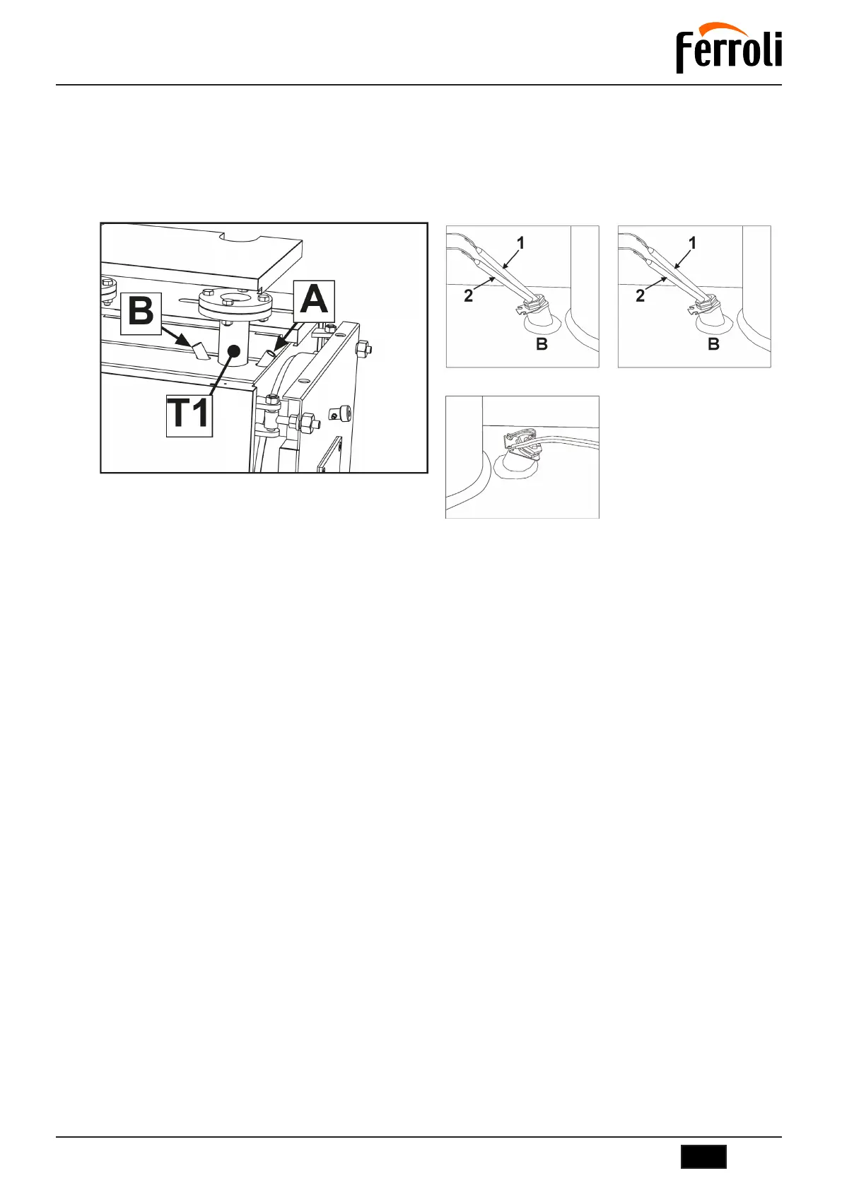
5.9 Probe and bulb positioning
The control panel is equipped with a temperature probe and three bulbs.
There are two wells “A” and “B” near the heating delivery “T1” (see fig. 15).
IT IS MANDATORY to insert in the well “A” (fig. 17) the temperature probe “4” and the safety thermostat bulb “3”.
Insert in the well “B” (fig. 16), the bulb of the 1st stage thermostat (1) and that of the 2nd stage thermostat (2).
Make sure the probe and bulbs reach the end of the sheath.
Place the capillaries of the bulbs and probe as shown in fig. 18.
fig. 15 - Probe and bulb wells
fig. 16 - Well B
fig. 17 - Well A
fig. 18
Legend
1 Thermostat bulb 1st Stage
2 Thermostat bulb 2nd Stage
3 Safety Thermostat bulb
4 Temperature probe
IMPORTANT
TO INSTALL ANOTHER TYPE OF TEMPERATURE CONTROL, IT IS NECESSARY TO USE AND INSTALL (AS PREVIOUSLY DE-
SCRIBED) A SAFETY THERMOSTAT COMPLYING WITH THE CURRENT REGULATIONS, WITH INTERVENTION TEMPERATURE
(SWITCHING POINT) = 110-6°C.
Bekijk gratis de handleiding van Ferroli TP3 COND 65÷1000, stel vragen en lees de antwoorden op veelvoorkomende problemen, of gebruik onze assistent om sneller informatie in de handleiding te vinden of uitleg te krijgen over specifieke functies.
Productinformatie
| Merk | Ferroli |
| Model | TP3 COND 65÷1000 |
| Categorie | Niet gecategoriseerd |
| Taal | Nederlands |
| Grootte | 14988 MB |