Extron MLC 64 RS VC D handleiding
Handleiding
Je bekijkt pagina 20 van 72
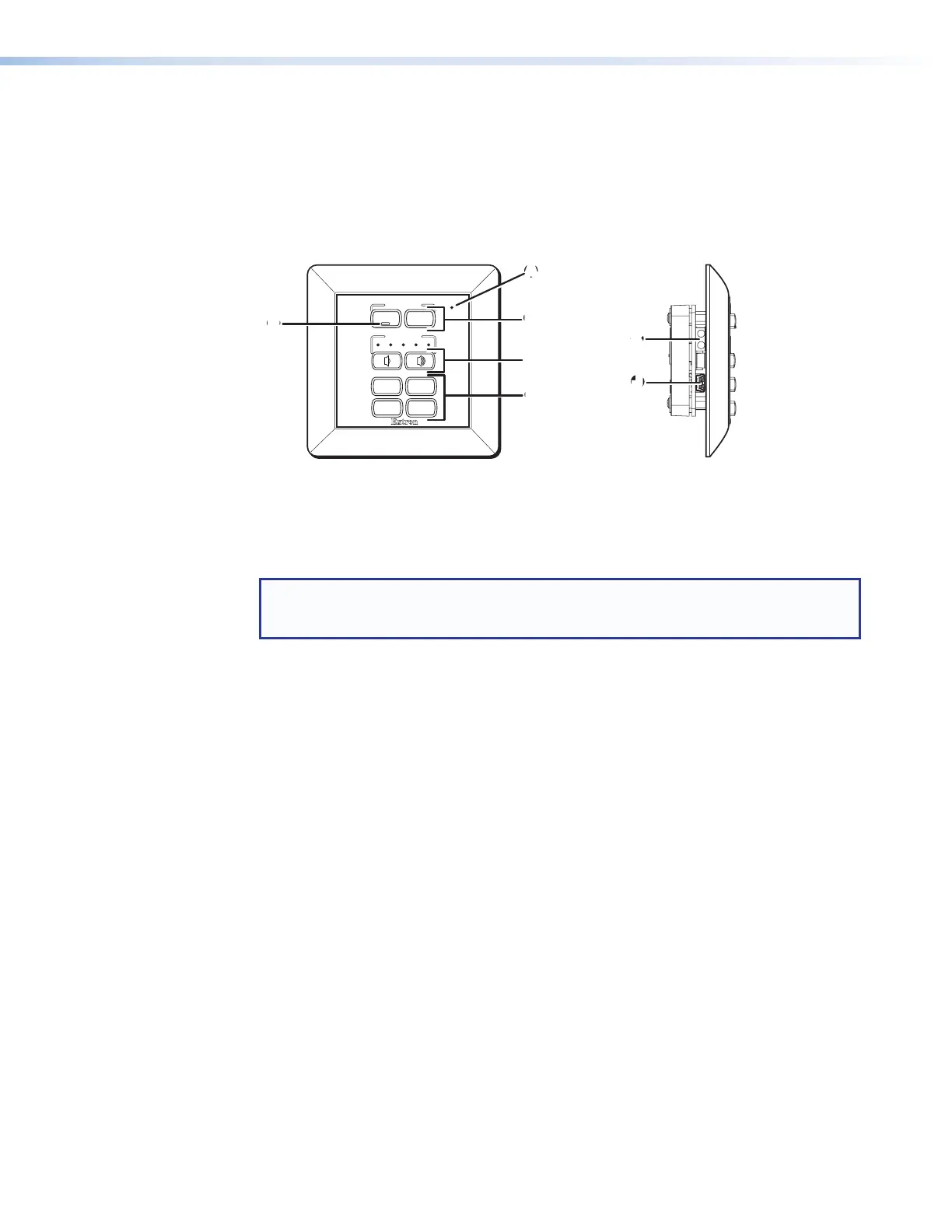
MLC 62 RS EU and MLC 62 RS MK Front and Side Panels
The MLC 62 RS EU and MLC 62 RS MK front panels contain the same buttons and
indicators as the MLC 62 D models. Other connectors and controls are on the left side
panel. To access these features, you must remove the MLC from the installation surface.
When the MLC is removed, the wall frame is released from the mounting surface as well,
leaving the metal mounting bracket in place (see Accessing the MLC 62 RS EU and
MLC 62 RS MK Side and Rear Panel Features on page 42 for removal procedures).
CC
A
A
VOLUME
DISPLAY
LAPTOP MUTE
PC VIDEO
ON OFF
E
BB
DD
EE
KK
JJ
A
Activity LED
B
Display power On and Off Buttons
C
Volume buttons and LEDs
D
Input Selection buttons
E
ON button identification nub
J
USB configuration port
K
IR Learning sensor
Figure 9. MLC 62 RS EU and MLC 62 RS MK Front and Side Panels
NOTE: The MLC 62 RS MK is the same size and has the same front and side panel
features as the MLC 62 RS EU, with the exception of its larger wall frame, which fits over
an MK electrical box.
Front Panel Features
A
Activity LED — This bicolored LED lights green when the MLC front panel buttons
are pressed. It blinks red while enabling front panel lockout (executive mode).
B
Display power On and Off buttons — After configuring these buttons, use them to
turn the connected display device or switcher on and off.
The face of the ON button contains a nub (
E
), which helps you to identify the button
by touch. When the ON button is pressed, it blinks rapidly while the connected device
is warming up. When the OFF button is pressed, it blinks slowly while the device
is cooling down. When this delay period has elapsed, the power button that was
pressed remains brightly lit. By default, only one of these two buttons can be selected
(active) at a time. Using the MLC configuration software, you can associate other
functions and relays with each of these buttons (see the MLC 60 Series Help file).
C
Volume buttons and LEDs (MLC 62 models only) — Use these buttons to adjust
the audio volume. Each VOLUME button blinks when pressed and continues to blink
while being held. The volume indicator LEDs above the buttons give indications of
change to the volume level as follows:
• When the RS-232 or IR/S port has been configured with a serial driver that
contains a volume table, the five LEDs light in order from left to right to show
volume level increments.
• If the current driver does not contain a volume table, the first two LEDs on the left
blink each time the VOLUME Down button is pressed, and the last two LEDs on the
right blink each time the VOLUME Up button is pressed, indicating a volume level
decrement or increment.
MLC 60 Series MediaLink Controllers • Features, Installation, and Operation 12
Bekijk gratis de handleiding van Extron MLC 64 RS VC D, stel vragen en lees de antwoorden op veelvoorkomende problemen, of gebruik onze assistent om sneller informatie in de handleiding te vinden of uitleg te krijgen over specifieke functies.
Productinformatie
| Merk | Extron |
| Model | MLC 64 RS VC D |
| Categorie | Niet gecategoriseerd |
| Taal | Nederlands |
| Grootte | 12439 MB |


