Extron IPCP Pro 360 handleiding
Handleiding
Je bekijkt pagina 35 van 72
IPCP Pro Series • Hardware Features and Installation
27
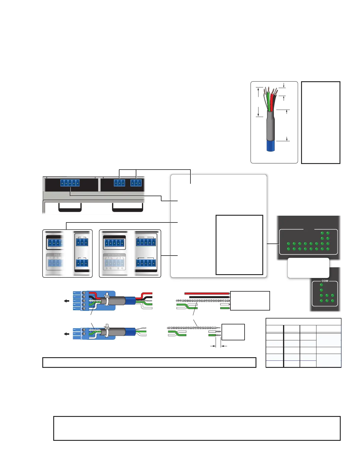
Bidirectional Control and Communication Connections and Features
D
3-pole COM ports, RS-232 only (see figure 16, figure 17, and figure 18 on page 20 through
page 22) and
E
5-pole COM ports, RS-232/RS-422/RS-485 — Use COM ports for serial control of a display or other
device and to receive status messages from the connected devices. These ports can send commands from a
driver file. RS-232 is the only mode for the 3-pole ports and is the default mode for the 5-pole ports.
IPCP Pro Series serial protocol:
• 300 to 115200 baud (9600 baud = default)
• 8 (default) or 7 data bits
• 1 (default) or 2 stop bits
• No parity (default), even parity, or odd parity
• Flow control support (default = none):
• 3-pole ports: software-only (XON, XOFF)
• 5-pole ports: hardware and software
Use the following diagram as a guide to cable the IPCP to other devices.
GTx Rx GTx Rx
COM 2 COM 3
COM 1
GTx Rx
RTS CTS
G
RELA
2
1
C
Tx Rx G Tx Rx G
RTS
Tx Rx G Tx Rx G
RTSCTS
CTS
COM 1
GTx Rx
RTS CTS
IR/SERIAL
1
S
G
2
S
G
1 7
8
4
GTx Rx Tx Rx
COM 2 COM
RELAYS
2
1
4
3
C
Tx
Rx
Tx
Rx
RTS
CTS
COM
1 2 3 4 5 6 7 8
COM
2 31
Rx
CTS
RTS
Tx
NOTE: If you use cable that has a drain wire, tie the drain wire to ground at both ends.
Projector, Panel
Display, PC, or Other
RS-232, RS-422, or
RS-485 Device
RS-232-
Controllable
Device
Receive (Rx)
Transmit (Tx)
Transmit
Receive
Receive (Rx)
Transmit (Tx)
Ground
Request to send
Clear to send
Transmit
Rx Receive
Tx
CTS
RTS
G Ground
Rx
G
Tx
Strip wires
3/16" (5 mm) max.
Front Panels, Rack Mount Models
5-pole COM
(RS-232, RS-422, RS-485)
3-pole COM
(RS-232)
Serial (COM) Ports
Front/Top Panel, DIN Rail Models
5-pole COM
(RS-232, RS-422, RS-485)
3-pole COM
(RS-232)
Select protocol via software.
COM port default protocol:
• 9600 baud
• 8 data bits • 1 stop bit
• no parity • no ˜ow contr ol
NOTE: The 5-pole
COM ports
support both
hardware and
software ˜ow
control.
The 3-pole COM
ports support
software ˜ow
control only.
To 3-pole
COM port
To 5-pole
COM port
RTS =
Request to Send
CTS = Clear to Send
Tx = Transmitting Data
Rx = Receiving Data
Rear Panels, Rack Mount Models
or or
Heat Shrink
Heat Shrink
Over Shield Wires
RS-232
Tx
Rx
Ground
RTS
CTS
RS-422
Tx-
Rx-
Ground
Tx+
Rx+
RS-485
Ground
5-pole COM Pin Configurations
Data-
(pins 1 & 2
tied together)
Data+
(pins 4 & 5
tied together)
Pin
1 (Tx)
2 (Rx)
3 (G)
4 (RTS)
5 (CTS)
Figure 24. Wiring COM ports for Serial Control
For bidirectional serial communication, the transmit, ground, and receive pins must be wired at both the
IPCP Pro Series and the other device. Each projector or other device may require different wiring. For details,
see the manual for that equipment or read the Extron device driver communication sheet, which is included
with the drivers.
NOTE: Maximum distances between the IPCP and the device being controlled are generally up to
200 feet (61 m) but can vary based on factors such as cable gauge, baud rates, environment, and output
levels from the IPCP and the device being controlled.
3/16"
(5 mm)
Max.
7/8"
(22 mm)
Heat Shrink
on Outer
Jacket to
Inner
Conductor
Transition
Extron
STP 20-2P Cable
TIP:
STP 20-2P
cable, shown
at left, is
recommended
for these
connections.
For best
results,
insulate the
common or
drain wires
using heat
shrink.
Bekijk gratis de handleiding van Extron IPCP Pro 360, stel vragen en lees de antwoorden op veelvoorkomende problemen, of gebruik onze assistent om sneller informatie in de handleiding te vinden of uitleg te krijgen over specifieke functies.
Productinformatie
| Merk | Extron |
| Model | IPCP Pro 360 |
| Categorie | Niet gecategoriseerd |
| Taal | Nederlands |
| Grootte | 11958 MB |


