EXSYS EX-44343 handleiding
Handleiding
Je bekijkt pagina 1 van 2
6 5 1
BESCHREIBUNG & TECHNISCHE DATEN
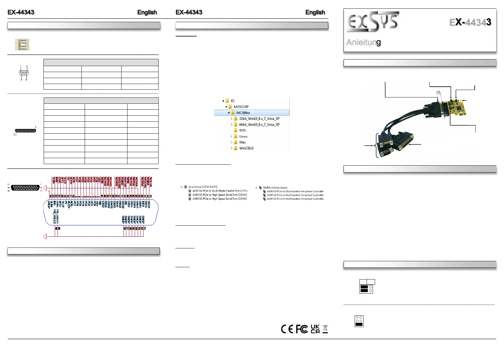
AUFBAU
Anleitung
Vers. 1.1 / 16.09.25
EX-44343
Kompatibilität: PCI-Express p1-x1 bis x16
Betriebssysteme: DOS / Windows 9x / ME / NT / 2000 / XP / Vista / 7 / 8.x / 10 / 11 /
Server 20xx / Linux / Mac OS
Anschlüsse: 2x 9-Pin Sub-D Seriell Stecker, 1x 25-Pin Sub-D Parallel Buchse
Lieferumfang: EX-44343, Oktopus Kabel, Low Profile Bügel, Treiber CD,
Anleitung
CONNECTORS & JUMPER SETTINGS
Die EX-44343 ist eine PCI-Express Multi I/O Karte mit einem Parallel Centronics EPP/ECP Port
und zwei seriellen FIFO 16C55x Ports, für den Anschluss von High-Speed seriellen RS-232
Peripherie Geräten (z.B. Terminal, Modem, Plotter usw.). Der serielle PCI-Express Bus unter-
stützt dabei optimal die Leistung des schnellen 16C55x Chipsets mit 16byte FIFO Cache. Die
EX-44343 gewährleistet so eine sichere Datenübertragung und exzellente Performance von bis
zu 115KBaud/s für jedes angeschlossene Gerät! Sie unterstützt alle PCI-Express Slots von x1
bis x16. Es ist nicht möglich die I/O Adressen und Interrupts manuell einzustellen, da die Ein-
stellungen der Karte vom System (BIOS) und beim Installieren des Betriebssystems automa-
tisch vorgenommen werden.
Switzerland:
EXSYS Vertriebs GmbH
Dübendorfstrasse 17
8602 Wangen
www.exsys.ch
Germany:
EXSYS Vertriebs GmbH
Industriestrasse 8
61449 Steinbach
www.exsys.de
Italy:
EXSYS Italia Srl
Via Belvedere, 45/B
I-22100 Como
www.exsys.it
S1 & S2:
9-Pin seriell
Anschluss
P1: 25-Pin parallel
Anschluss
Bi-Direktional
JP1: Power auf 9 Pin
Stecker Ein/Aus
JP2: Jumper für die
Stromquelle (Netzteil)
oder PCIe Bus
J5: Anschluss
für PC-Netzteil
J2+J3: 10-Pin interner
Serieller Anschluss
44 Pin D-Sub Buchse
für das Octopus-Kabel
ANSCHLÜSSE & JUMPER EINSTELLUNGEN
DIS PWR
S1
S2
JP1: DIS = Am Pin 9 liegt das Standard Signal RI (Ring Indicator).
(Werkseinstellung)
PWR = Am Pin 9 kann jetzt eine Spannung von DC5V oder
DC12V eingestellt werden.
Die Einstellung der Spannung nehmen sie mit JP2 vor. Dies sollte aber
bei Standard Anwendungen nicht verstellt werden.
JP2: Wenn sie den Jumper JP1 für S1 bis S4 auf PWR gesetzt haben,
können sie jetzt mit dem JP2 den Spannungswert einstellen. Es gibt 3
verschiedene Spannungsquellen. (Nur in Verbindung mit JP1 auf PWR!)
AUX 5V = 5Volt vom PC-Netzteil
AUX 12V = 12Volt vom PC-Netzteil
PCI 12V = 12Volt vom Mainboard (STANDARD)
AUX5V
AUX12V
PCI12V
1 +5V
2 GND
3 GND
4 +12V
J5:
For power from the power supply, J5 must be connected to the PC power
supply!
DB25F:
Parallel 25-Pin Sub-D Female Connector
Pin Signal Pin Signal Pin Signal
1 STROBE 10 ACKNOWLEDGE 19 GROUND
2 DATA 0 11 BUSY 20 GROUND
3 DATA 1 12 PAPER EMPTY 21 GROUND
4 DATA 2 13 SELECT 22 GROUND
5 DATA 3 14 AUTO FEED 23 GROUND
6 DATA 4 15 ERROR 24 GROUND
7 DATA 5 16 INIT 25 GROUND
8 DATA 6 17 SELECT INPUT
9 DATA 7 18 GROUND
DB9M:
Serial 9-Pin Sub-D Connector
Pin Signal Pin Signal Pin Signal
1 CDC 4 DTR 7 RTS
2 RXD 5 GROUND 8 CTS
3 TXD 6 DSR 9 RI
DB 44F:
HARDWARE INSTALLATION
If you are ready with the jumper settings, please proceed with the following installation
instructions. Because the designs of computers are different, only general installation
instructions are given. Please refer your computer’s reference manual whenever in doubt.
1. Turn off the power to your computer and any other connected peripherals.
2. Remove the mounting screws located at the rear and/or sides panels of your Comput-
er and gently slide the cover off.
3. Locate an available expansion slot and remove its covers from the rear panel of your
computer. Make sure it is the right expansion slot for the card (see card description)
4. Align the card with the expansion slot, and then gently but firmly, insert the card. Make
sure the card is seated and oriented correctly. Never insert the card by force!
5. Then connect the card with a screw to the rear panel of the computer case.
6. Gently replace your computer’s cover and the mounting screws.
DRIVER INSTALLATION
Windows
After completing the hardware installation, the operating system will automatically the card and
install this! If the driver should not be installed automatically, insert the driver CD into you CD-
ROM drive (eg drive D:) and then open the folder „IO/MOSCHIP/MCS99xx“. Please select the
folder with your operating system and install the driver (see Picture). Follow the hardware
assistant and finish the installation. Important! Restart your PC in any case after installing the
drivers.
Use the following driver for the following Windows Server Version.
Windows Server 2003 = XP Driver
Windows Server 2008 = VISTA Driver
Windows Server 2008R2 = Windows 7 Driver
Windows Server 2012 = Windows 8.x Driver
Windows Server 2012R2 to Server 2025 = Windows 10 Driver
CHECK INSTALLED DRIVER
Open the >Device manager<. Now you should see at „Ports (COM & LPT)“ and at
„Multifunction Adapter“ the following new entry's:
If you see this or a similar information the device is installed correctly.
CHANGE PORT NUMBER
If you like to change the port number for example COM3 to COM5, open the „Device Manager”
click at „COM3”, „Settings” and then „Advance”. There you can change between COM3 till
COM256.
MS-DOS
Please read the manual on the driver CD. You will find the manual in the following folder
„IO/MOSCHIP/MCS99xx/DOS“.
LINUX
The required Linux driver are located in the following directory „IO/MOSCHIP/MCS99xx/Linux“.
Bekijk gratis de handleiding van EXSYS EX-44343, stel vragen en lees de antwoorden op veelvoorkomende problemen, of gebruik onze assistent om sneller informatie in de handleiding te vinden of uitleg te krijgen over specifieke functies.
Productinformatie
| Merk | EXSYS |
| Model | EX-44343 |
| Categorie | Niet gecategoriseerd |
| Taal | Nederlands |
| Grootte | 744 MB |
Caratteristiche Prodotto
| Kleur van het product | Black, Brown |
| Gewicht | 550 g |
| Breedte | 120 mm |
| Diepte | 66 mm |
| Stroomvoorziening | 3.3V |


