EXSYS EX-42372 handleiding
Handleiding
Je bekijkt pagina 5 van 8
12
English Seriell RS-422/485 PCI Board
4. Hardware Installation
•
Turn the system power OFF before installation!
•
Use static electricity discharge precautions.
•
Remove the chassis cover from your computer
•
Locate an unused PCI slot (typically white or ivory) and remove the correspond-
ing slot cover from computer chassis.
•
Plug the RS422/485 PCI card to the unused PCI expansion slot and attached
the I/O card bracket to the computer chassis screw.
•
Put the chassis cover back on the computer.
•
Turn ON the power of your computer and peripherals.
•
Proceed with Software Driver Installation.
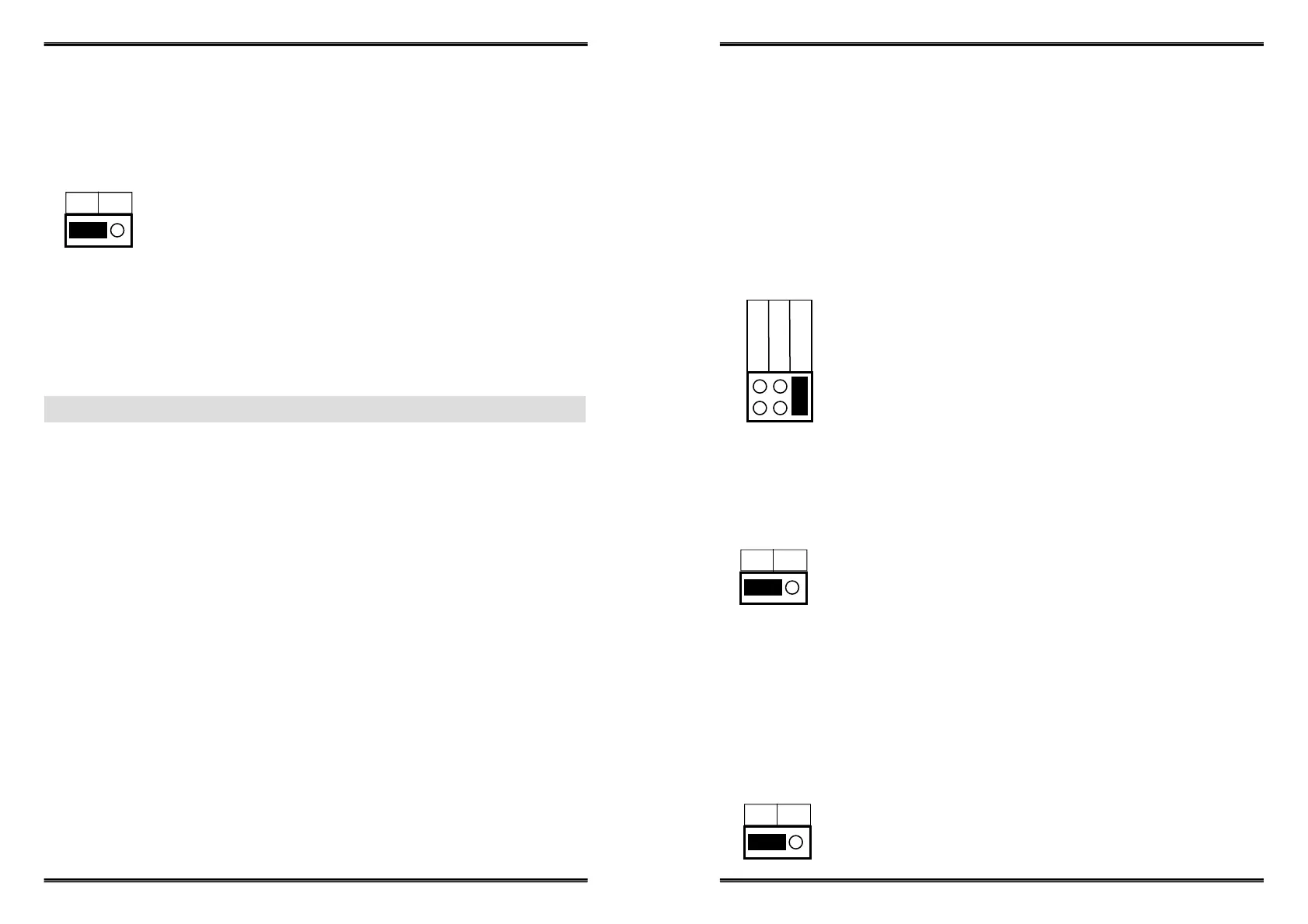
4. TXD Control Setting:
This jumper is used to select the control signal for the transmitter buffer in RS485 2-
wire mode. There are 2 settings are selectable, one is “MAN” (manually) the other
one is “AUT” (automatically, factor default), please keep it at “AUT” in all cases.
MAN AUT
AUT = TXD Control is Automatic (Default)
ON = TXD Control is Manual
(Needs to be Configured Manually in the Device Manager)
JP1 for S1 Port
JP2 for S2 Port
5. Factory Use Only Connectors (J1):
This connector is only used for factory production purpose, please don’t install any
jumper or cable on it!
5
Seriell RS-422/485 PCI Karte Deutsch
485-2W
485-4W
422
Es gibt zwei Jumper-Reihen um die Ports S1 und S2 einzustellen
1. Mode Einstellungs-Jumper: JP5 für S1 und JP6 für S2
2. Abschlusswiderstand Jumper: JP7 für S1 und JP8 für S2
3. Echo oder No Echo Jumper: JP3 für S1 und JP4 für S2
4. TXD Control Einstellungs-Jumper: JP1 für S1 und JP2 für S2
3.3 Jumper-Einstellung
2. Abschlusswiderstand Ein/Aus:
JP5 für S1 Port
JP6 für S2 Port
485-2W = RS-485 Mode mit 2 Draht Leitung (Werkseinstellung)
485-4W = RS-485 Mode mit 4 Draht Leitung
422 = RS-422 Mode
Diese Jumper aktiviert oder deaktiviert den 120 Ohm Abschlusswiderstand zwi-
schen DATA+ und DATA– des RS-485 Transceiver:
1. Mode Einstellungen für S1 und S2 Ports:
JP7 für S1 Port
JP8 für S2 Port
OFF ON
OFF = Abschlusswiderstand Ausgeschaltet (Werkseinstellung)
ON = Abschlusswiderstand Eingeschaltet
Der “Echo Mode” ist für das Anwendungsprogramm nützlich um zu erkennen ob der
RS-485 “Bus” in einem Konflikt steht. Sind die zurückgesendeten Daten nicht die
gleichen was gesendet wurde, ist der RS-485 Bus überlastet und die Daten werden
nicht korrekt übermittelt. Diese Einstellung betrifft nur den RS-485 Mode mit 2 Draht.
Es hat keinen Einfluss auf die Modi RS-485 mit 4 Draht oder RS-422.
3. Echo oder No Echo Einstellung:
JP3 für S1 Port
JP4 für S2 Port
OFF ON
OFF = No Echo Data (Werkseinstellung)
ON = Echo bei der Übermittlung der Daten
Bekijk gratis de handleiding van EXSYS EX-42372, stel vragen en lees de antwoorden op veelvoorkomende problemen, of gebruik onze assistent om sneller informatie in de handleiding te vinden of uitleg te krijgen over specifieke functies.
Productinformatie
| Merk | EXSYS |
| Model | EX-42372 |
| Categorie | Niet gecategoriseerd |
| Taal | Nederlands |
| Grootte | 1184 MB |
Caratteristiche Prodotto
| Connectiviteitstechnologie | Bedraad |
| Soort serieële aansluiting | RS-422/485 |
| Ondersteunt Windows | Windows 2000, Windows 7 Ultimate, Windows 98, Windows ME, Windows Vista Ultimate, Windows XP Professional |
| Intern | Ja |
| Bedrijfstemperatuur, bereik | 32 - 131 °F |


