Eaton Green Motion XCI000411 handleiding
Handleiding
Je bekijkt pagina 49 van 107
7.2 Load balancing
7.2.1 Load balancing parameters
The relevant parameters for understanding load balancing by the Eaton load balancing algorithm are described in the
table below.
7.2.2 Static load balancing
For static load balancing the Eaton load balancing algorithm uses the parameter Maximum current for the charging
site as the total available current for EV chargers. The algorithm then divides this current over the EV
chargers, considering:
•
Number of cars connected
•
Maximum current capacity per car
•
EV charger priority
The parameter Prioritize this charger determines the importance the Eaton load balancing algorithm attaches to each
EV charger. This parameter can differ from one EV charger to the next.
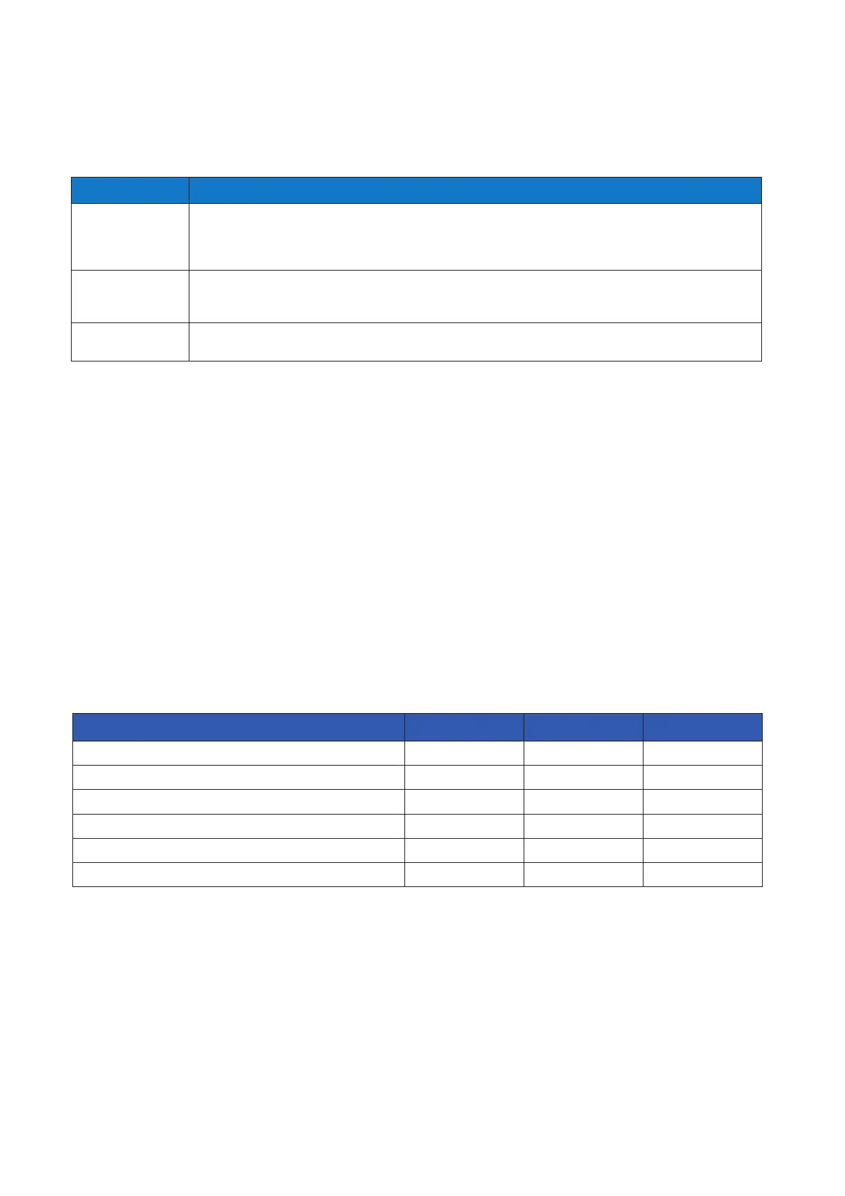
Table 15. Load balancing parameters
Parameter Description
Maximum current for the
charging site [A]
The maximum current [A] the local electrical infrastructure can supply to the EV chargers.
This value ensures that the combined load of the EV chargers never exceeds the maximum current dedicated to the
EV charging electrical infrastructure.
This value is fixed and is used by the algorithm for both static and dynamic load balancing.
Maximum current for the
building[A]
The maximum current [A] capacity of the local electrical infrastructure including, but not limited to, the EV charging
electrical infrastructure.
This value is fixed and is used by the algorithm for dynamic load balancing.
Prioritize this charger The EV charger set as priority will be provided with the maximum available current for faster charging. Then the remaining current is shared
between the EV chargers without priority.
Example
Three EV chargers will be installed in a building with a maximum current capacity of 100 A. The maximum load of all
other installed equipment is 60 A. The electrical infrastructure supplying the EV chargers can supply 50 A. There is no
energy meter present. EV charger 1 is configured as Master. EV charger 2 and 3 are configured as nodes. EV charger
1 is also reserved for an essential service vehicle that should always be charged as fast as possible. The parameters
for the three EV chargers in this case should be as follows:
(6)
The electrical infrastructure supplying the EV chargers can supply 50 A, however the maximum load of all other
installed equipment is 60 A. Maximum current capacity – maximum load of all other installed equipment =
Maximum available current for EV charging. 100 A – 60 A = 40 A.
EV charger 1 EV charger 2 EV charger 3
Dynamic load balancing enabled No N/A N/A
Mode Master Node Node
Phase balancing limit See Section 7.3 N/A N/A
Energy meter enabled No N/A N/A
Maximum current for the charging site
(6)
40 A N/A N/A
Prioritize this charger Yes No No
Table 16. Example of static load balancing
49GREEN MOTION BUILDING INSTALLATION MANUAL MN191028EN April 2024 www.eaton.com
Bekijk gratis de handleiding van Eaton Green Motion XCI000411, stel vragen en lees de antwoorden op veelvoorkomende problemen, of gebruik onze assistent om sneller informatie in de handleiding te vinden of uitleg te krijgen over specifieke functies.
Productinformatie
| Merk | Eaton |
| Model | Green Motion XCI000411 |
| Categorie | Niet gecategoriseerd |
| Taal | Nederlands |
| Grootte | 16416 MB |
