Eaton Green Motion XCI000411 handleiding
Handleiding
Je bekijkt pagina 35 van 107
Refer to Section 6.2 for recommendations regarding the connection to the grid.
If the earthing system is a TT or a TN, the ground resistance must not exceed 100 Ohms. Power supply can be
protected with a surge protection device type 2.
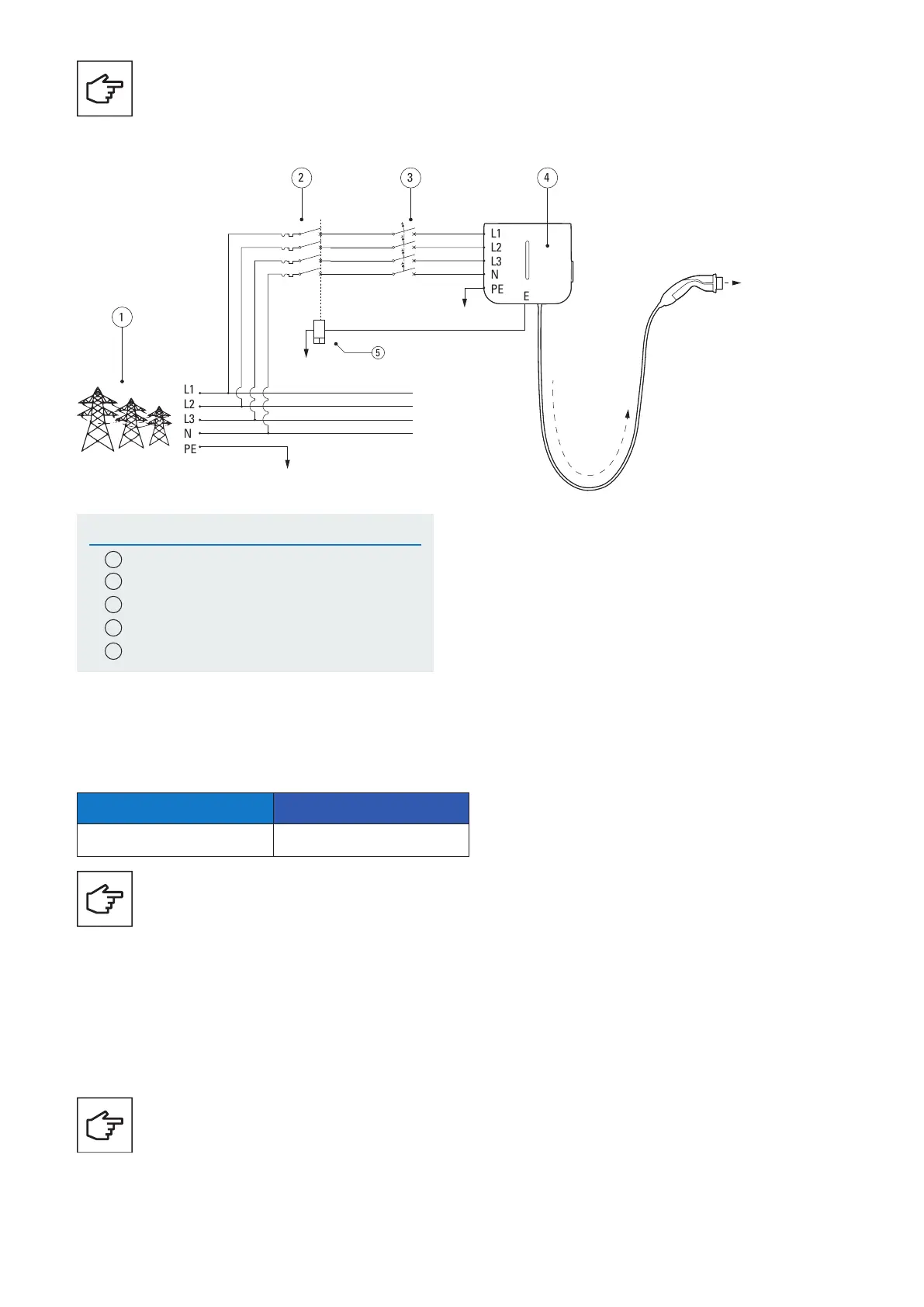
Figure 16. The Green Motion Building EV charger wiring diagram with external switching device
Tag Description
1
Grid
2
Circuit breaker
3
Type A RCD according to IEC 61851-1:2017
4
Green Motion Building EV charger
5
Shunt trip
4
L1
L2
L3
N
PE
L1
L2
L3
N
PE
E
3
2
1
Type Eaton reference
Tripping coil/Shunt Trip ZP-ASA/24
Table 12. Recommended tripping coil/shunt trip
The terminal E (Emergency) is located on the control unit.
To connect your shunt trip to the Green Motion Building. EV charger follow these steps:
Step 1. Ensure unit is powered off and load is disconnected.
Step 2. Wire the mating connector. Mating connector reference:
• Manufacturer: Weidmuller (Pluggable Terminal Blocks B2L 3.50/20/180 SN BK BX)
• Manufacturer part number: 1727710000
6.5.2 Installation of an external switching device
Eaton recommends the use of the following tripping coil/shunt trip:
Please be advised that the recommended tripping coil/shunt trip ZP-ASA/24 will not fit onto a one module sized,
1P+N circuit breaker.
The mating connector is not provided with the charger and is to be obtained separately.
35GREEN MOTION BUILDING INSTALLATION MANUAL MN191028EN April 2024 www.eaton.com
Bekijk gratis de handleiding van Eaton Green Motion XCI000411, stel vragen en lees de antwoorden op veelvoorkomende problemen, of gebruik onze assistent om sneller informatie in de handleiding te vinden of uitleg te krijgen over specifieke functies.
Productinformatie
| Merk | Eaton |
| Model | Green Motion XCI000411 |
| Categorie | Niet gecategoriseerd |
| Taal | Nederlands |
| Grootte | 16416 MB |
