DoorBird D1101KH handleiding
Handleiding
Je bekijkt pagina 13 van 68
ENGLISH
13
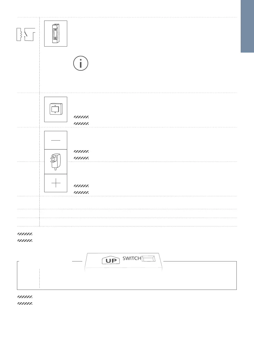
R1, R1 Bi-stable latching relay #1, max. 24 V DC/AC, 1 A. Security feature: The relay
keeps its state even in the case of loss of power. You can configure the default
state of the relay (open/close) via the DoorBird App. These ports can be used
to connect e.g. an electric door opener. The device does not supply power to
the connected device. The power supply for the electric door opener must be
installed separately.
When wiring an electric door opener directly to a door station, there is a
risk that the electric door opener could be tampered by unauthorized
third parties (e. g. by breaking the door station and short-circuiting the
wiring of the door opener). Therefore, we generally recommend the use of
a remote safety relay mounted indoors (e. g. DoorBird I/O Door Controller
A1081) for wiring an electric door opener for a more secure installation in
your home.
E1, E1 Digital input (0 V, 0 A (NO)), for door opener button, max. 0 V DC/AC, 0 A.
These ports can be used to connect e.g. a door opener button inside the home. It
will can trigger the bi-stable latching relay of the device (R1, R1)
NOTICE
Please make sure to add no voltage on these ports. Extra voltage may
destroy the device immediately.
15 VDC - 15 V DC Power supply input, negative pole (-). Please connect the black wire of
the power supply unit (mains adapter) supplied with this device if you do not
power the device using PoE. We only recommend PoE.
NOTICE
Do not power the device simultaneously via the power supply from the
power supply unit (mains adapter) and the power supply via PoE.
15 VDC + 15 V DC Power supply input, positive pole (+). Please connect the red wire of the
power supply unit (mains adapter) supplied with the device here, if you do not
power the device using PoE. We only recommend PoE.
NOTICE
Do not power the device simultaneously via the power supply from the
power supply unit (mains adapter) and the power supply via PoE.
COM 1 Jack for authorized peripherals of Bird Home Automation which will be released
in the future, e.g. keypad
CB 2 Jack for second call button.
CB 1 Jack for first call button.
NOTICE
The jacks “CB1”, “CB2” and “COM1” on the rear side of the Main Electrical Unit must only be used to
connect components certified by Bird Home Automation.
CALL BUTTON PORT
SWITCH
(4 PIN)
Use the four wire call-button cable provided to connect the call-button to the Main
Electrical Unit (already connected in delivery condition to the jack ”CB1“/ ”CB2“).
NOTICE
Please take care when connecting the cables and wires. Connecting the cables and wires the wrong way
may damage the device. Wires without insolation material must not protrude out of the green screw
connection terminal, it may lead to electrical short and damage the device.
R1
R1
Bekijk gratis de handleiding van DoorBird D1101KH, stel vragen en lees de antwoorden op veelvoorkomende problemen, of gebruik onze assistent om sneller informatie in de handleiding te vinden of uitleg te krijgen over specifieke functies.
Productinformatie
| Merk | DoorBird |
| Model | D1101KH |
| Categorie | Niet gecategoriseerd |
| Taal | Nederlands |
| Grootte | 8861 MB |
Caratteristiche Prodotto
| Kleur van het product | Black, Stainless steel |
| Gewicht | 1595 g |
| Breedte | 214 mm |
| Diepte | 48 mm |
| Hoogte | 179 mm |


