Dometic VMD 2.5 Display handleiding
Handleiding
Je bekijkt pagina 4 van 56
EN
Modes Features
• Cool
• Heat
• Auto
• Fan only
• Eco mode
• Quiet mode
• Scheduler can run up to four programs
• Selectable set point differential settings
• Selectable fan and pump operating speeds
• Adjustable low and high fan speeds
• Auxiliary electric heater connection/control
• Auto power source detection/management
• Zone assignment
• Filter hour counter/notification
• Display units in imperial or metric measurements
• Screen lock out
• Active alarm indicator
9 Specifications
This section lists the operating specifications for the display.
Ambient operating temperature range –
0.4 °F (–
18 °C)… 179.6 °F (82 °C)
Maximum Rh conditions 99 % Non-condensing
Set point operating range 65.0 °F (18.33 °C)… 85.0 °F (29.44 °C)
Ambient temperature display range 5 °F (–
15 °C)… 132.0 °F (55.55 °C)
Sensor accuracy ± 2 °F at 77 °F (± 38 °F (1 °C) at 77 °F (25 °C)
Supply voltage type 12 V
10 Pre-installation
This section describes the actions to complete prior to installing the display.
WARNING! ELECTRICAL SHOCK, FIRE, AND/OR EXPLOSION HAZ-
ARD.
Failure to obey the following warnings could result in death or serious injury:
• Prior to cutting or drilling, disconnect the power supply.
• Verify that there are no obstacles such as wires or pipes inside the cab-
in's walls at the display mounting location.
NOTICE!
Do NOT locate the display panel in direct sunlight, near any heat-producing
appliances, or in a bulkhead where temperatures radiating from behind the
panel may affect performance.
10.1 Choosing the display location
• Inside wall of the cabin, out of direct sunlight
• Slightly higher than mid-height of the cabin wall
• An area with freely circulating air
• A maximum distance of 75.0 (22.86 m) from the air conditioner
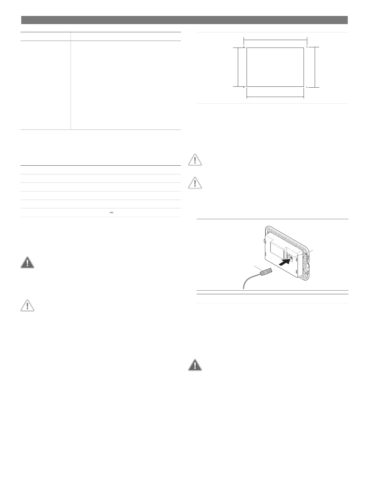
10.2 Preparing the mounting location
1. Disconnect the power supply.
1.9 in (49 mm) 2.2 in (55 mm)
3.5 in (88 mm)
2.9 in (74 mm)
2. Mark the dimensions of the opening and the screw hole locations on the cabin wall.
3. Cut out the opening.
4. Drill four screw holes.
11 Installation
NOTICE!
Do NOT use a screw gun and do NOT overtighten the screws when mounting
the display.
NOTICE!
Do NOT staple sensor cables during installation.
This section describes how to install the display.
1. Route one end of the display cable through the electrical control box of the air con-
ditioner and plug it into the jack on the circuit board.
1
2
1 Display cable 2 Jack
2. Route the other end of the display cable through the wall opening and plug it into
the jack on the back of the display.
3. Use the screws to secure the display to the cabin wall.
4. Snap the bezel (optional) onto the display.
12 Operation
WARNING! ELECTRICAL SHOCK.
Failure to obey this warning could result in death or serious injury.
The display remains powered when the power control is off. Disconnect the
power supply prior to performing any maintenance on the display.
This system utilizes variable speed technology, which allows the compressor to operate
for long periods instead of constantly cycling on and off. The benefits include increased
reliability, reduced energy consumption, improved de-humidification, and lower oper-
ating noise levels.
4
Bekijk gratis de handleiding van Dometic VMD 2.5 Display, stel vragen en lees de antwoorden op veelvoorkomende problemen, of gebruik onze assistent om sneller informatie in de handleiding te vinden of uitleg te krijgen over specifieke functies.
Productinformatie
| Merk | Dometic |
| Model | VMD 2.5 Display |
| Categorie | Niet gecategoriseerd |
| Taal | Nederlands |
| Grootte | 7105 MB |


