Dantherm HCV 700 handleiding
Handleiding
Je bekijkt pagina 28 van 60
28
INSTALLATION & SERVICE MANUAL FOR PROFESSIONALS
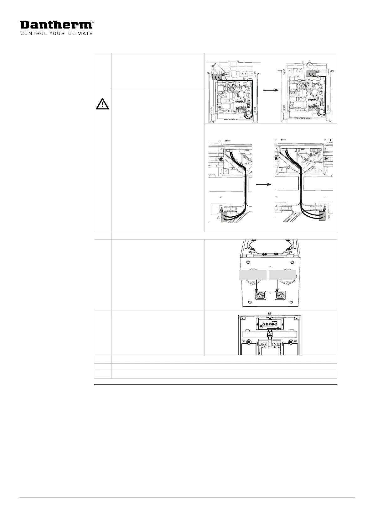
Installation Options: Switching between modes A and B
8 Move the cable port, incl. hu-
midity sensor (and VOC sensor, if
present), to the sensor position for
mode B.
HCV 400-460
CAUTION
Insucient device performance
and ventilation eect
To ensure optimal device
performance, all wired accessories
must be tted correctly.
• Make sure that the distance
between the sensor head and
the cable port is 50mm to
ensure correct measurements
of humidity level (and air
quality).
• All other wired accessories
must be swapped/installed
according to the current
operating mode A/B.
HCV 300-500-700
9 Ret the main PCB cover/control panel.
10 Switch the drain hose and set it to
mode B as indicated.
For a further description of how
to install the drain hose, see page
33.
11 Change the lter (ONLY if the op-
tional pollen lter F7 is used).
• Check the table on page 17
to determine the correct posi-
tion of the F7 lter in mode A/B.
12 Connect the 4 ducts as indicated on the label and as described on page 35.
13 Calibrate the unit as described on page 37.
14 Ret the front and top part of the front cover.
Warning
Caution
Mode B Mode A
Bekijk gratis de handleiding van Dantherm HCV 700, stel vragen en lees de antwoorden op veelvoorkomende problemen, of gebruik onze assistent om sneller informatie in de handleiding te vinden of uitleg te krijgen over specifieke functies.
Productinformatie
| Merk | Dantherm |
| Model | HCV 700 |
| Categorie | Niet gecategoriseerd |
| Taal | Nederlands |
| Grootte | 4620 MB |


