Handleiding
Je bekijkt pagina 35 van 49
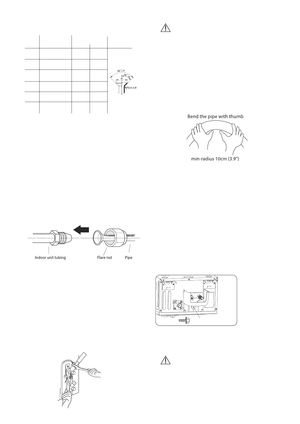
ST4.8*12 screw
PIPING EXTENSION BEYOND FLARE FORM
Pipe
gauge
Φ6.35
(Φ1/4”)
Φ9.52
(Φ3/8”)
Φ12.7
(Φ1/2”)
Tightening
Torque
Flare dimension (A)
(UnitL mm/inch)
Flare Shape
8.4/0.33 8.7/0.34
13.2/0.52 13.5/0.53
16.2/0.64 16.5/0.65
19.2/0.76 19.7/0.78
23.2/0.91 23.7/0.93
26.4/1.04 26.9/1.06
Min. Max.
Φ16
(Φ5/8”)
Φ19
(Φ3/4”)
Φ22
(Φ7/8”)
18-20 N.m
(180-200kgf.cm)
32-39 N.m
(320-390kgf.cm)
49-59 N.m
(490-590kgf.cm)
57-71 N.m
(570-710kgf.cm)
67-101 N.m
(670-1010kgf.cm)
85-110 N.m
(850-1100kgf.cm)
8. Remove the flaring tool an flare form,
then inspect the end of the pipe for cracks
and even flaring.
Connect the copper pipes to the indoor unit
first, then connect it to the outdoor unit. You
should first connect the low-pressure pipe,
then the high-pressure pipe.
1. When connecting the flare nuts, apply a
thin coat of refrigeration oil to the flared
ends of the pipes.
2. Align the center of the two pipes that you
will connect.
3. Tighten the flare nut as tightly as possible
by hand.
4. Using a spanner, grip the nut on the unit
tubing.
5. While firmly gripping the nutm use a
torque wrench to tighten the flare nut
according to the torque values in above
table.
Step 4: Connect pipes
NOTE: Use both a spanner and a torque
wrench when connecting or disconnecting
pipes to/from the unit.
NOTE: DO NOT intertwine signal cable with
other wires. While bundling these items
togetherm do not intertwine or cross the
signal cable with any other wiring
Carefully bend the tubing in the middle
according to the diagram below. DO NOT
bend the ybing more than 90º or more than 3
times.
NOTE ON MINIMUM BEND RADIUS
• Ensure to wrap insulation around the
piping. DIrect contact with the bare piping
may result in burns or frostbite.
• Make sure the pipe is properly connected.
Over tightening may damage the bell mouth
and under tightening may lead to leakage.
CAUTION
Check to make sure there is no refrigerant
leak after completing the installatio work. If
there is a refrigerant leak, bentilate the area
immediately and evacuate the system (Refer
to the Air Evacuation section of this manual.
CAUTION
6. After connecting the copper pipes to the
indoor unit, wrap the power cable, signal
cable and the piping together with
binding tape.
7. Thread this pipeline through the wall and
connect it to the outdoor unit.
8. Insulate all the piping , including the
valves of the outdoor unit.
9. Fix the water receiver (supplied in Acces-
sories box) to the indoor unit by a screw.
10. Open the stop valves of the outdoor unit
to start the flow of the refrigerant
between the indoor and outdoor unit.
NOTICE
Two ST4.8*12
screws are
supplied, one of
which is spare.
Page 35
Bekijk gratis de handleiding van Daizuki DX1C18426-21, stel vragen en lees de antwoorden op veelvoorkomende problemen, of gebruik onze assistent om sneller informatie in de handleiding te vinden of uitleg te krijgen over specifieke functies.
Productinformatie
| Merk | Daizuki |
| Model | DX1C18426-21 |
| Categorie | Airco |
| Taal | Nederlands |
| Grootte | 6253 MB |


