Daikin VKM50GBV1 handleiding
Handleiding
Je bekijkt pagina 8 van 20
4 3P130767-4K English
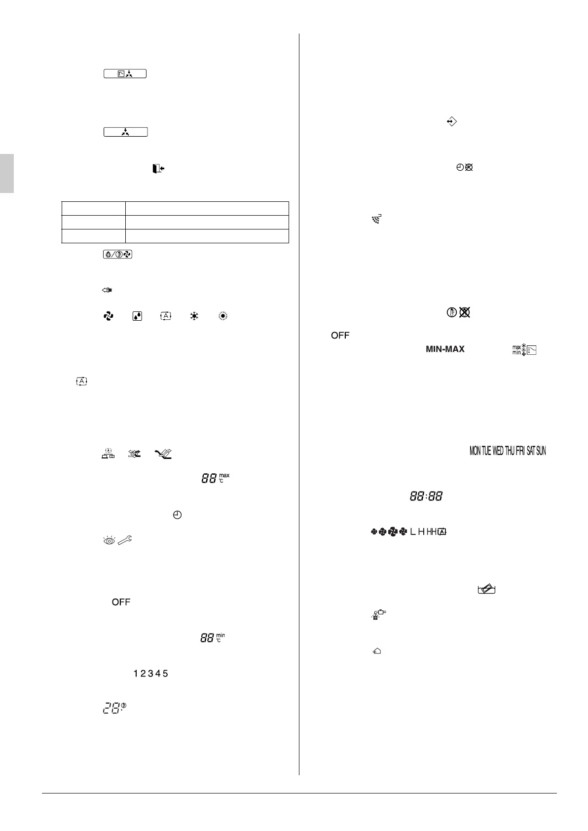
2 Operation lamp (red)
The lamp lights up during operation or blinks if a malfunc-
tion occurs.
3 Display “ ” (changeover under control)
May be displayed when combined with a VRV-system air
conditioner.
It is impossible to changeover heat/cool with the remote
controller when this icon is displayed.
4 Display “ ” (under centralized control)
When this display shows, the system is under centralized
control. (This is not a standard specification.)
5 LEAVE HOME ICON “ ”
The leave home icon shows the status of the leave home
function.
6Display
“”
(defrost/hot start)
It may be displayed when freezing of outdoor unit’s coil
increases in heating mode.
7 Display “ ” (air purifier)
This display shows that the air cleaning unit is in operation.
8Display
“”
“”
“”
“”
“”
(operation
mode: “FAN, DRY, AUTOMATIC, COOLING, HEATING”)
This displays the operating status of the combined air con-
ditioner.
• There is no “heating” for the VRVIII system (Cooling only
type).
• “ ” is only available for systems operating in cooling
and heating at the same time.
9 Remote controller thermo
This detects the temperature around the remote controller.
This is not the same as the temperature of return air from
room (RA) by heat exchanger unit.
10 Display “ ” “ ” “ ”
This displays the ventilation mode.
11 MAXIMUM SET TEMPERATURE “ ”
The maximum set temperature indicates the maximum set
temperature when in limit operation.
12 SCHEDULE TIMER ICON “ ”
This icon indicates that the schedule timer is enabled.
13 Display
“”
(inspection/test operation)
When the inspection/test operation button is pressed, the
display shows the mode in which the system actually is.
• Do not use under usual use (service person/installer
only).
14 OFF ICON “ ”
This icon indicates that the OFF action is selected when
programming the schedule timer.
15 MINIMUM SET TEMPERATURE “ ”
The minimum set temperature indicates the minimum set
temperature when in limit operation.
16 ACTION ICONS “ ”
These icons indicate the actions for each day of the sched-
ule timer.
17 Display
“”
(set temperature)
This displays the set temperature of the combined air con-
ditioner.
It is not displayed when the unit is used as an independent
system.
18 Ventilation mode selector button
This is pressed to switch the ventilation mode.
19 Fan speed control button
This is pressed to control the fan speed.
(Refer to item 30)
20 Inspection/test operation button
Not used, for service purpose only.
21 PROGRAMMING BUTTON “ ”
This button is a multi-purpose button.
Depending on the previous manipulations of the user, the
programming button can have various functions.
22 SCHEDULE TIMER BUTTON “ ”
This button enables or disables the schedule timer.
23 Programming time button
Use this button for programming start and/or stop time.
24 Display
“”
(air flow flap)
This displays the direction and mode of the air flow flap of
the combined air conditioner.
25 Temperature setting button
Use this button for setting the desired temperature of air
conditioner combined with this unit.
This button can’t use for this unit.
This unit can’t change temperature setting.
26 SETPOINT/LIMIT BUTTON “ ”
This button toggles between setpoint, limit operation or
(programming mode only).
27 OPERATION CHANGE/ BUTTON “ ”
This button is a multi-purpose button. Depending on the
previous manipulations of the user, it can have following
functions:
28 DAY OF THE WEEK INDICATOR “ ”
The day of the week indicator shows the current week day
(or the set day when reading or programming the schedule
timer).
29 CLOCK DISPLAY “ ”
The clock display indicates the current time (or the action
time when reading or programming the schedule timer).
30 Display
“”
(fan speed)
This display shows the fan speed you have selected.
This is only displayed when the fan speed selection but-
ton is pressed. It normally displays the set fan strength of
the combined air conditioner.
31 ELEMENT CLEANING TIME ICON “ ”
This icon indicates the element must be cleaned.
32 Display
“”
(time to clean air filter)
Refer to “4.1 WHEN TO PERFORM MAINTENANCE OF
THE AIR FILTER”.
33 Display “ ” (ventilation)
This display shows that the total heat exchange is in operation.
34 Display “NOT AVAILABLE”
• “NOT AVAILABLE” may be displayed for a few seconds if
the function for the button pressed is not available for the
unit or the air conditioner.
• “NOT AVAILABLE” is only displayed when none of the
indoor units is equipped with the function in question
when running several units simultaneously. It is not dis-
played if the function is available on even one of the
units.
ON Leave home is enabled.
FLASHING Leave home is active.
OFF Leave home is disabled.
C
1 Select The operation mode of the installation (FAN,
DRY, AUTOMATIC, COOLING, HEATING).
2 Toggle between minimum temperature and
maximum temperature when in limit operation.
01_EN_3P130767-4K.fm 4 ページ 2013年3月21日 木曜日 午前11時50分
Bekijk gratis de handleiding van Daikin VKM50GBV1, stel vragen en lees de antwoorden op veelvoorkomende problemen, of gebruik onze assistent om sneller informatie in de handleiding te vinden of uitleg te krijgen over specifieke functies.
Productinformatie
| Merk | Daikin |
| Model | VKM50GBV1 |
| Categorie | Niet gecategoriseerd |
| Taal | Nederlands |
| Grootte | 2744 MB |


