Daikin VAM2000J8VEB handleiding
Handleiding
Je bekijkt pagina 27 van 32
17 Technical data
Installation and operation manual
27
VAM350~2000J8VEB
Heat reclaim ventilation unit
4P664011-1 – 2021.08
17 Technical data
▪ A subset of the latest technical data is available on the regional
Daikin website (publicly accessible).
▪ The full set of latest technical data is available on the Daikin
Business Portal (authentication required).
17.1 Wiring diagram
The wiring diagram can be found on the outside of the service cover.
Legend for wiring diagrams:
A1P Printed circuit board
A2P Printed circuit board assy (fan)
(VAM350~650)
A2P-A3P Printed circuit board assy (fan)
(VAM800+1000)
A2P~A5P Printed circuit board assy (fan)
(VAM1500+2000)
C7 Capacitor (M1F)
F1U (A1P) Fuse (250V, 6.3A, T)
F2U (A2P) Fuse (250V, 5A, T) (VAM350~650)
F3U Fuse (250V, 6.3A, T) (VAM800~2000)
F4U (A2P) Fuse (250V, 6.3A, T) (VAM350~650)
HAP Pilot lamp (service monitor - green)
K*R Magnetic relay
L*R Reactor
M1D Motor (damper)
M2D Motor (damper) (VAM1500+2000)
M1F Supply air fan
M2F Exhaust air fan
M3F Motor (exhaust air fan) (top)
(VAM1500+2000)
M4F Motor (supply air fan) (top)
(VAM1500+2000)
PS Switching power supply
Q1DI Field earth leak detector (≤300mA)
R* Resistance
R1T Thermistor (indoor air)
R2T Thermistor (outdoor air)
R3T Thermistor (PTC)
S1C Limit switch damper motor
S2C Limit switch damper motor
(VAM1500+2000)
V1R Diode bridge
X1M (A1P) Terminal
X2M (A1P) Terminal (outside input)
X3M Terminal (power supply)
Z1F Noise filter
Z*C Noise filter (ferrite core)
Remote controller
SS1 Selector switch
Connector for option
X14A Connector (CO
2
sensor)
X24A Connector (outside damper)
X33A Connector (contact printed circuit board)
X35A Connector (power supply printed circuit
board)
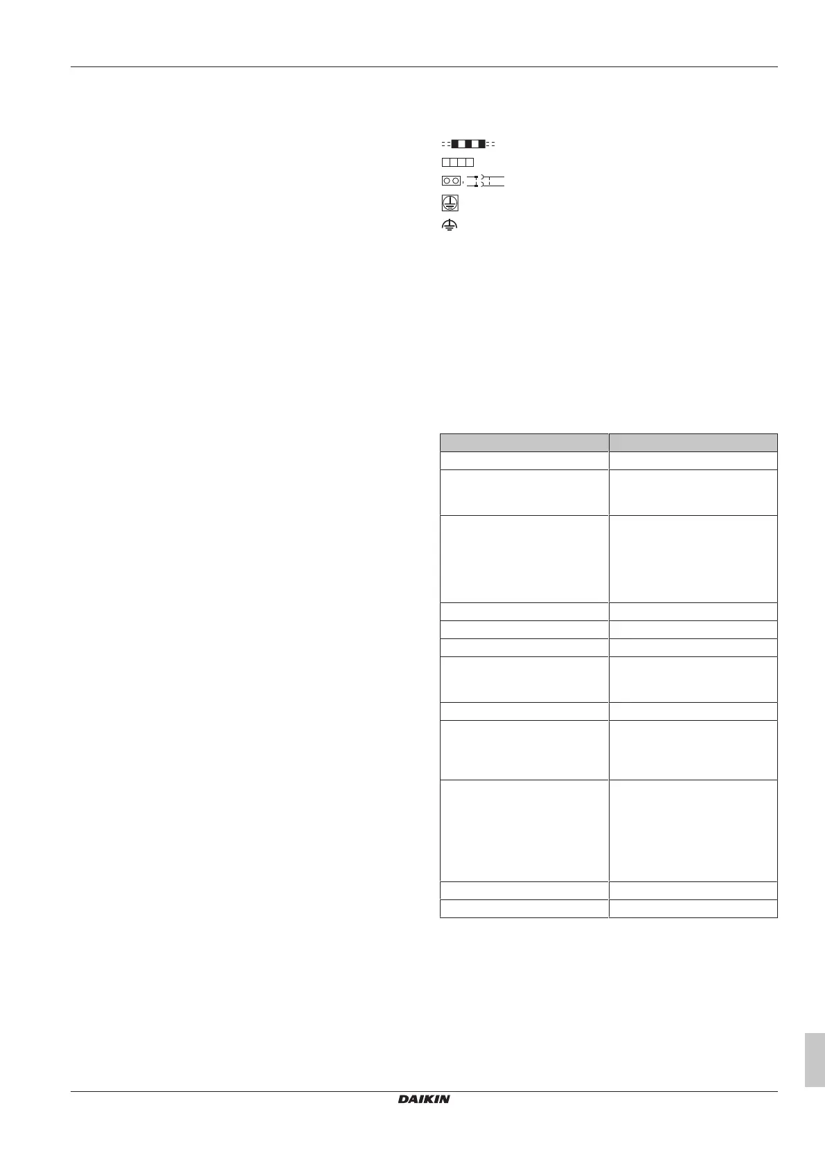
Symbols:
Field wiring
Terminals
Connectors
Protective earth
Noiseless earth
Colours:
BLK Black
BLU Blue
BRN Brown
GRN Green
ORG Orange
RED Red
WHT White
YLW Yellow
Translation of text on wiring diagram
English Translation
Notes Notes
X35A is connected when optional
accessories are being used, see
wiring diagram of this accessory
X35A is connected when optional
accessories are being used, see
wiring diagram of this accessory
An EKVDX unit and its
corresponding VAM-J8 unit
should be connected to a
common power supply. Refer to
the installation manual of the
EKVDX unit for further details.
An EKVDX unit and its
corresponding VAM-J8 unit
should be connected to a
common power supply. Refer to
the installation manual of the
EKVDX unit for further details.
Transmission wiring Transmission wiring
Ext. output - error state External output - error state
Ext. output - R32 alarm External output – R32 alarm
Caution when performing service
inside the el. compo. box
Caution when performing service
inside the electrical component
box.
Caution for ELECTRIC SHOCK Caution for ELECTRIC SHOCK
Do not open the el. compo. box
cover for 10 minutes after the
power supply is turned off.
Do not open the electrical
component box cover for 10
minutes after the power supply is
turned off.
After opening the el. compo. box,
measure (on A1P~A5P) the
points shown at the right with a
tester and confirm that the
voltage of the capacitor in the
main circuit is less than DC50V.
After opening the electrical
component box, measure (on
A1P~A5P) the points shown at
the right with a tester and confirm
that the voltage of the capacitor
in the main circuit is less than
DC50V.
Measuring points for voltage Measuring points for voltage
Printed circuit board Printed circuit board
Bekijk gratis de handleiding van Daikin VAM2000J8VEB, stel vragen en lees de antwoorden op veelvoorkomende problemen, of gebruik onze assistent om sneller informatie in de handleiding te vinden of uitleg te krijgen over specifieke functies.
Productinformatie
| Merk | Daikin |
| Model | VAM2000J8VEB |
| Categorie | Niet gecategoriseerd |
| Taal | Nederlands |
| Grootte | 4596 MB |


