Handleiding
Je bekijkt pagina 38 van 52
10 About the system
Installation and operation manual
38
SERHQ020~032BAW1 + SEHVX20~64BAW
Split packaged air-cooled water chiller
4P508019-1D – 2019.11
WHT White
YLW Yellow
A1P Main PCB circuit 1
A2P User interface PCB
A3P Control PCB circuit 1
A4P Demand PCB (optional)
A5P Main PCB circuit 2
A6P Demand PCB (optional)
A7P Remote user interface PCB (optional)
A8P Control PCB circuit 2
C1~C3 Filter capacitor
F1U (A*P) Fuse (250V, 3.15A, T)
HAP (A*P) PCB LED
K11E Electronic expansion valve (circuit 1)
K21E Electronic expansion valve (circuit 2)
K1P Pump contactor
K1S Pump overcurrent relay
K*R (A3P) PCB relay
M1P Pump
Q1T Thermostat for expansion vessel heater
PS (A*P) Switching power supply
Q1DI Earth leakage circuit breaker (field supply)
R1T Thermistor (air, fin)
R11T Leaving water thermistor (circuit 1)
R12T Returning water thermistor (circuit 1)
R13T Refrigerant liquid thermistor (circuit 1)
R14T Refrigerant gas thermistor (circuit 1)
R21T Leaving water thermistor (circuit 2)
R22T Returning water thermistor (circuit 2)
R23T Refrigerant liquid thermistor (circuit 2)
R24T Refrigerant gas thermistor (circuit 2)
S1L Flow switch (circuit 1)
S2L Flow switch (circuit 2)
S1S Thermostat input 1 (field supply)
S2S Thermostat input 2 (field supply)
S3S Operation ON input (field supply)
S4S Operation OFF input (field supply)
SS1 (A1P, A5P) Selector switch (emergency)
SS1 (A2P) Selector switch (master/slave)
SS1 (A7P) Selector switch (master/slave) (optional)
V1C, V2C Ferrite core noise filter
X1M~X4M Terminal strip
X801M (A*P) Printed circuit board terminal strip
Z1F, Z2F (A*P) Noise filter
For the user
10 About the system
NOTICE
Do not use the system for other purposes. In order to avoid
any quality deterioration, do not use the unit for cooling
precision instruments or works of art.
NOTICE
For future modifications or expansions of your system:
A full overview of allowable combinations (for future
system extensions) is available in technical engineering
data and should be consulted. Contact your installer to
receive more information and professional advice.
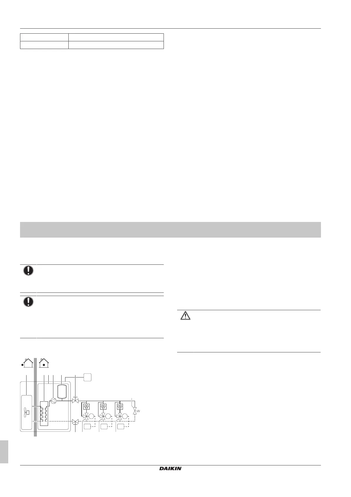
10.1 System layout
RC
RT1
M1
RT2
M2
RT3
M3
FC1 FC2 FC3
a c e f
f
g g g
h
db
a Outdoor unit
b Indoor unit
c Plate heat exchanger
d Pump
e Expansion vessel
f Shut-off valve
g Motorized valve
h Bypass valve
FC1…3 Fancoil unit (field supply)
RC User interface
RT1…3 Room thermostat
11 User interface
CAUTION
▪ NEVER touch the internal parts of the controller.
▪ Do NOT remove the front panel. Some parts inside are
dangerous to touch and appliance problems may
happen. For checking and adjusting the internal parts,
contact your dealer.
This operation manual offers a non-exhaustive overview of the main
functions of the system.
Refer to the operation manual of the user interface for information
about the display and the buttons of the user interface.
Bekijk gratis de handleiding van Daikin SEHVX40BAW, stel vragen en lees de antwoorden op veelvoorkomende problemen, of gebruik onze assistent om sneller informatie in de handleiding te vinden of uitleg te krijgen over specifieke functies.
Productinformatie
| Merk | Daikin |
| Model | SEHVX40BAW |
| Categorie | Airco |
| Taal | Nederlands |
| Grootte | 8378 MB |


