Handleiding
Je bekijkt pagina 37 van 52
9 Technical data
Installation and operation manual
37
SERHQ020~032BAW1 + SEHVX20~64BAW
Split packaged air-cooled water chiller
4P508019-1D – 2019.11
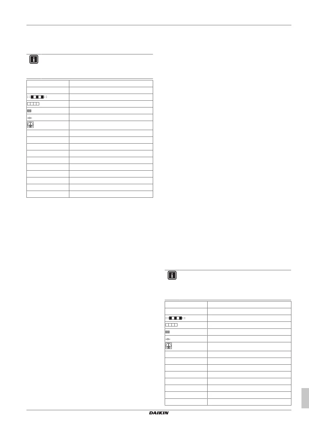
9.5 Wiring diagram: Outdoor unit
Refer to the wiring diagram sticker on the outdoor unit. The
abbreviations used are listed below:
INFORMATION
The wiring diagram on the outdoor unit is only for the
outdoor unit. For the indoor unit or optional electrical
components, refer to the wiring diagram of the indoor unit.
L1,L2,L3 Live
N Neutral
Field wiring
Terminal strip
Connector
Terminal
Protective earth (screw)
BLK Black
BLU Blue
BRN Brown
GRN Green
GRY Grey
ORG Orange
PNK Pink
RED Red
WHT White
YLW Yellow
A1P~A7P Printed circuit board
BS1~BS5 Pushbutton switch (mode, set, return, test,
reset)
C1, C63, C66 Capacitor
DS1, DS2 DIP switch
E1HC~E3HC Crankcase heater
F1U Fuse (650V, 8A, B) (A4P) (A8P)
F1U, F2U Fuse (250 V, 3.15 A, T) (A1P)
F5U Field fuse
F400U Fuse (250 V, 6.3 A, T) (A2P)
H1P~H8P Pilot lamp (service monitor - orange)
H2P blinks: under preparation or in test
operation
H2P lights up: malfunction detection
HAP Pilot lamp (service monitor - green)
K1 Magnetic relay
K2 Magnetic contactor (M1C)
K2M, K3M Magnetic contactor (M2C, M3C)
K1R, K2R Magnetic relay (K2M, K3M)
K3R~K5R Magnetic relay (Y1S~Y3S)
K6R~K9R Magnetic relay (E1HC~E3HC)
L1R Reactor
M1C ~M3C Motor (compressor)
M1F, M2F Motor (fan)
PS Switching power supply (A1P, A3P)
Q1DI Earth leakage circuit breaker (field supply)
Q1RP Phase reversal detection circuit
R1T Thermistor (fin) (A2P)
R1T Thermistor (air) (A1P)
R2T Thermistor (suction)
R4T Thermistor (coil-deicer)
R5T Thermistor (coil-outlet)
R6T Thermistor (liquid-pipe receiver)
R7T Thermistor (accumulator)
R10 Resistor (current sensor) (A4P) (A8P)
R31T~R33T Thermistor (discharge) (M1C ~M3C)
R50, R59 Resistor
R95 Resistor (current limiting)
S1NPH Pressure sensor (high)
S1NPL Pressure sensor (low)
S1PH, S3PH Pressure switch (high)
S1S Selector switch (fan, cool/heat) (optional
cool/heat selector)
S2S Selector switch (cool/heat) (optional cool/
heat selector)
SD1 Safety devices input
T1A Current sensor (A6P, A7P)
V1R Power module (A4P, A8P)
V1R, V2R Power module (A3P)
X1A, X4A Connector (M1F, M2F)
X1M Terminal strip (power supply)
X1M Terminal strip (control) (A1P)
X1M Terminal strip (A5P)
Y1E, Y2E Expansion valve (electronic type) (main,
subcool)
Y1S Solenoid valve (hotgas bypass)
Y2S Solenoid valve (oil return)
Y3S Solenoid valve (4-way valve)
Y4S Solenoid valve (injection)
Z1C~Z7C Noise filter (ferrite core)
Z1F Noise filter (with surge absorber)
9.6 Wiring diagram: Indoor unit
Refer to the wiring diagram sticker on the indoor module. The
abbreviations used are listed below:
INFORMATION
The wiring diagram on the outdoor module is only for the
outdoor module. For the hydro module or optional electrical
components, refer to the wiring diagram of the hydro
module.
L1,L2,L3 Live
N Neutral
Field wiring
Terminal strip
Connector
Terminal
Protective earth (screw)
BLK Black
BLU Blue
BRN Brown
GRN Green
GRY Grey
ORG Orange
PNK Pink
RED Red
Bekijk gratis de handleiding van Daikin SEHVX40BAW, stel vragen en lees de antwoorden op veelvoorkomende problemen, of gebruik onze assistent om sneller informatie in de handleiding te vinden of uitleg te krijgen over specifieke functies.
Productinformatie
| Merk | Daikin |
| Model | SEHVX40BAW |
| Categorie | Airco |
| Taal | Nederlands |
| Grootte | 8378 MB |


