Handleiding
Je bekijkt pagina 21 van 52
6 Configuration
Installation and operation manual
21
SERHQ020~032BAW1 + SEHVX20~64BAW
Split packaged air-cooled water chiller
4P508019-1D – 2019.11
5.8.6 To install the user interface
The unit comes with a user interface offering a user-friendly way to
set up, use and maintain the unit. Before operating the user
interface, follow this installation procedure.
Wire specification Value
Type 2 wire
Section 0.75~1.25 mm
2
Maximum length 500 m
NOTICE
The wiring for connection is NOT included.
NOTICE
The user interface MUST be mounted indoors.
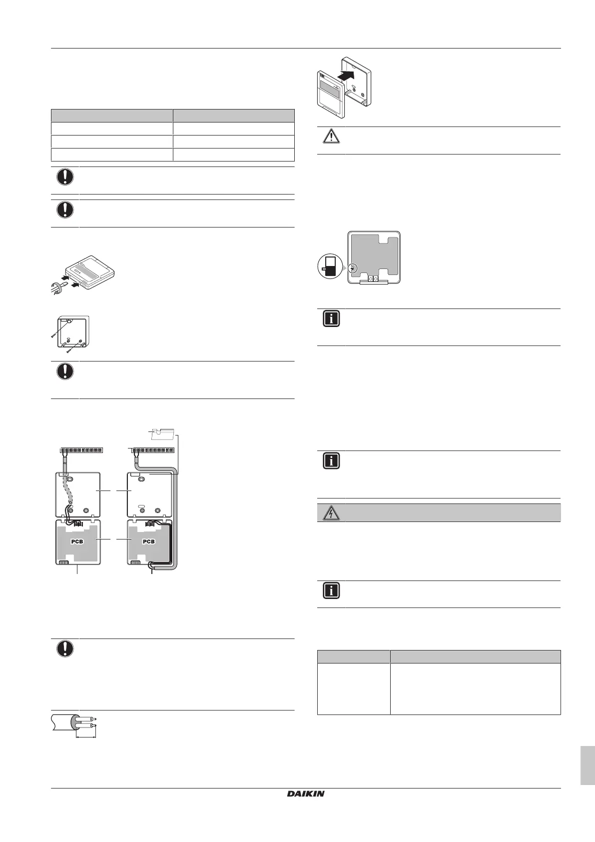
1 Insert a slotted screwdriver into the slots in the rear part of the
user interface, and remove the front part of the user interface.
2 Fasten the user interface on a flat surface.
NOTICE
Be careful NOT to distort the shape of the lower part of the
user interface by overtightening the mounting screws.
3 Connect the terminals of the user interface and the terminals
inside the unit (P1 to P1, P2 to P2) as shown in the figure.
P1P2
a
a
f
b
c
d e
P1P2
P2
P1
P2
P1
a Unit
b Rear part of the user interface
c Front part of the user interface
d Wired from the rear
e Wired from the top
f Use nippers to notch the part for the wiring to pass through
NOTICE
▪ When wiring, run the wiring away from the power
supply wiring in order to avoid receiving electric noise
(external noise).
▪ Peel the shield for the part that has to pass through the
inside of the user interface case (L).
L
4 Reattach the upper part of the user interface, starting with the
clips at the bottom.
1
CAUTION
Do NOT pinch the wiring when attaching.
If, in addition to the standard user interface, an optional user
interface (EKRUAHTB) is installed as well:
5 Connect the electrical wires of both user interfaces as
described.
6 Select a master and a slave user interface using the SS1
selector switch.
PCB
SS1
SS
M
S Slave
M Master
INFORMATION
Only the user interface set as master can be used as a
room thermostat.
5.8.7 To install optional equipment
For the installation of optional equipment, refer to the installation
manual which is delivered with the optional equipment or the
addenda delivered with this unit.
6 Configuration
INFORMATION
It is important that all information in this chapter is read
sequentially by the installer and that the system is
configured as applicable.
DANGER: RISK OF ELECTROCUTION
6.1 Making field settings
6.1.1 About making field settings
INFORMATION
The LEDs and buttons are located in the outdoor unit.
If required, carry out field settings according to the following
instructions. Refer to the service manual for more details.
Pushbuttons and DIP switches
Item Description
Pushbuttons By operating the pushbuttons it is possible to:
▪ Change the mode.
▪ Perform field settings (demand operation,
low noise, etc).
Bekijk gratis de handleiding van Daikin SEHVX40BAW, stel vragen en lees de antwoorden op veelvoorkomende problemen, of gebruik onze assistent om sneller informatie in de handleiding te vinden of uitleg te krijgen over specifieke functies.
Productinformatie
| Merk | Daikin |
| Model | SEHVX40BAW |
| Categorie | Airco |
| Taal | Nederlands |
| Grootte | 8378 MB |


