Daikin RXYSA8AMY1B handleiding
Handleiding
Je bekijkt pagina 52 van 56
23 Disposal
Installation and operation manual
52
RXYSA8~12AMY1B
VRV 5-S system air conditioner
4P752781-1C – 2024.10
c
h
a
d
e e
d
c c
d
e
f
j
l
i
g
b
kk
d
e
k
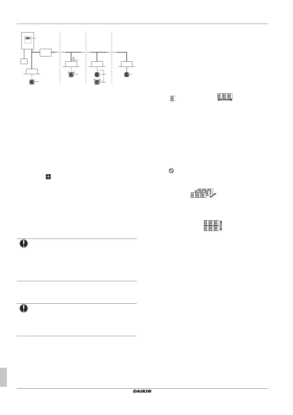
a Heat pump outdoor unit
b SV unit
c Refrigerant piping
d VRV direct expansion (DX) indoor unit
e Remote controller in normal mode and alarm only mode
f Remote controller in supervisor mode (mandatory in
some situations)
g Centralised controller (optional)
h Refrigerant leak
i Outdoor unit error code on 7‑segment display
j Error code 'A0–11' and audible alarm and red warning
signal is generated from this remote controller.
k Error code 'U9–01' is displayed on this remote controller.
No alarm or warning lights.
l Error code 'A0–11' and audible alarm and red warning
signal is generated from this supervisor remote
controller. The unit address is displayed on this remote
controller.
Note: It is possible to stop the leak detection alarm from the remote
controller and from the app. To stop the alarm from the remote
controller, press for 3seconds.
Note: Leak detection will trigger SVS output. For more information,
see "17.5To connect the external outputs"[440].
Note: An optional output PCB for the indoor unit can be added to
provide output for external device. The output PCB will trigger in
case a leak is detected. For exact model name see option list of the
indoor unit. For more information about this option, refer to the
installation manual of the optional output PCB
Note: Some centralised controllers can also be used as supervisor
remote controller. For further details on installation, please refer to
the installation manual of the centralised controllers.
NOTICE
The R32 refrigerant leakage sensor is a semiconductor
detector which may incorrectly detect substances other
than R32 refrigerant. Avoid using chemical substances
(e.g. organic solvents, hair spray, paint) in high
concentrations, in the close proximity of the indoor unit
because this may cause misdetection by the R32
refrigerant leakage sensor.
23 Disposal
NOTICE
Do NOT try to dismantle the system yourself: dismantling
of the system, treatment of the refrigerant, oil and other
parts MUST comply with applicable legislation. Units
MUST be treated at a specialised treatment facility for
reuse, recycling and recovery.
24 Technical data
▪ A subset of the latest technical data is available on the regional
Daikin website (publicly accessible).
▪ The full set of the latest technical data is available on the Daikin
Business Portal (authentication required).
24.1 Service space: Outdoor unit
When mounting units side by side, the piping route must be to the
front or downwards. In this case the piping route to the side is not
possible.
Single unit ( ) | Single row of units ( )
→ See "figure1"[42] on the inside of the front cover of this manual.
A,B,C,D Obstacles (walls/baffle plates)
E Obstacle (roof)
a,b,c,d,e Minimum service space between the unit and obstacles
A, B, C, D and E
e
B
Maximum distance between the unit and the edge of
obstacle E, in the direction of obstacle B
e
D
Maximum distance between the unit and the edge of
obstacle E, in the direction of obstacle D
H
U
Height of the unit
H
B
,H
D
Height of obstacles B and D
1 Seal the bottom of the installation frame to prevent
discharged air from flowing back to the suction side
through the bottom of the unit.
2 Maximum two units can be installed.
Not allowed
Note: For better serviceability, use a distance ≥250 mm for all
dimensions marked with 'a'.
Multiple rows of units ( )
→ See "figure2"[42] on the inside of the front cover of this manual.
Note: For better serviceability, use a side by side distance ≥250mm
(instead of ≥100mm as shown on the figures above).
Stacked units (max. 2 levels) ( )
→ See "figure3"[42] on the inside of the front cover of this manual.
A1=>A2 (A1) If there is danger of drainage dripping and freezing
between the upper and lower units…
(A2) Then install a roof between the upper and lower
units. Install the upper unit high enough above the lower
unit to prevent ice buildup at the upper unit's bottom
plate.
B1=>B2 (B1) If there is no danger of drainage dripping and
freezing between the upper and lower units…
(B2) Then it is not required to install a roof, but seal the
gap between the upper and lower units to prevent
discharged air from flowing back to the suction side
through the bottom of the unit.
Note: For better serviceability, use a side by side distance ≥250mm
(instead of ≥100mm as shown on the figures above).
Bekijk gratis de handleiding van Daikin RXYSA8AMY1B, stel vragen en lees de antwoorden op veelvoorkomende problemen, of gebruik onze assistent om sneller informatie in de handleiding te vinden of uitleg te krijgen over specifieke functies.
Productinformatie
| Merk | Daikin |
| Model | RXYSA8AMY1B |
| Categorie | Niet gecategoriseerd |
| Taal | Nederlands |
| Grootte | 9612 MB |


