Daikin RXYSA8AMY1B handleiding
Handleiding
Je bekijkt pagina 41 van 56
18 Configuration
Installation and operation manual
41
RXYSA8~12AMY1B
VRV 5-S system air conditioner
4P752781-1C – 2024.10
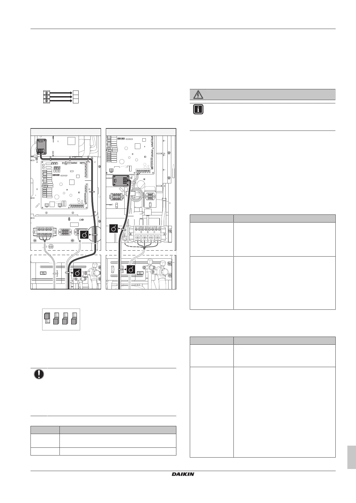
17.6 To connect the cool/heat selector
switch option
In order to control the cooling or heating operation from a central
location, the following optional cool/heat selector switch
(KRC19-26A) can be connected:
1 Connect the cool/heat selector switch to terminal X1M of the
cool/heat selector PCB.
KRC19-26A
1
2
3
A
B
C
X1M
X1M Terminal on the PCB
KRC19-26A Cool/heat selector switch
2 Route the wires in the switchbox as shown:
A6P
A6P
a
a
b
b
b
8 HP 10+12 HP
3 Turn ON the DIP switch (DS1‑1). See "18.1.2 Field setting
components"[442] for more information on the DIP switch.
OFF
ON
1 2 3 4
DS1 DIP switch 1
17.7 To check the insulation resistance
of the compressor
NOTICE
If, after installation, refrigerant accumulates in the
compressor, the insulation resistance over the poles can
drop, but if it is at least 1MΩ, then the unit will not break
down.
▪ Use a 500V mega-tester when measuring insulation.
▪ Do NOT use a mega-tester for low voltage circuits.
1 Measure the insulation resistance over the poles.
If Then
≥1MΩ Insulation resistance is OK. This procedure is
finished.
<1MΩ Insulation resistance is not OK. Go to the next step.
2 Turn ON the power and leave it on for 6hours.
Result: The compressor will heat up and evaporate any
refrigerant in the compressor.
3 Measure the insulation resistance again.
18 Configuration
DANGER: RISK OF ELECTROCUTION
INFORMATION
It is important that all information in this chapter is read
sequentially by the installer and that the system is
configured as applicable.
18.1 Making field settings
18.1.1 About making field settings
To continue the configuration of the VRV 5-S heat pump system, it is
required to give some input to the PCB of the unit. This chapter will
describe how manual input is possible by operating the push buttons
on the PCB and reading the feedback from the 7‑segment displays.
Next to making field settings it is also possible to confirm the current
operation parameters of the unit.
Push buttons and DIP switches
Item Description
Push buttons By operating the push buttons it is possible to:
▪ Perform special actions (refrigerant charge,
testrun, etc).
▪ Perform field settings (demand operation,
low noise, etc).
DIP switches By operating the DIP switches it is possible to:
▪ DS1 (1): COOL/HEAT selector (refer to the
manual of the cool/heat selector switch).
OFF=not installed=factory setting
▪ DS1 (2~4): NOT USED. DO NOT CHANGE
THE FACTORY SETTING.
▪ DS2 (1~4): NOT USED. DO NOT CHANGE
THE FACTORY SETTING.
See also:
▪ "18.1.2Field setting components"[442]
Mode 1 and 2
Mode Description
Mode 1
(monitoring
settings)
Mode1 can be used to monitor the current
situation of the outdoor unit. Some field setting
contents can be monitored as well.
Mode 2
(field settings)
Mode2 is used to change the field settings of
the system. Consulting the current field setting
value and changing the current field setting
value is possible.
In general, normal operation can be resumed
without special intervention after changing field
settings.
Some field settings are used for special
operation (e.g., one time operation, recovery/
vacuuming setting, manual adding refrigerant
setting, etc.). In such a case, it is required to
abort the special operation before normal
operation can restart. It will be indicated in
below explanations.
Bekijk gratis de handleiding van Daikin RXYSA8AMY1B, stel vragen en lees de antwoorden op veelvoorkomende problemen, of gebruik onze assistent om sneller informatie in de handleiding te vinden of uitleg te krijgen over specifieke functies.
Productinformatie
| Merk | Daikin |
| Model | RXYSA8AMY1B |
| Categorie | Niet gecategoriseerd |
| Taal | Nederlands |
| Grootte | 9612 MB |


