Daikin RXM25N2V1B9 handleiding
Handleiding
Je bekijkt pagina 42 van 68
6 | Installation
Installer reference guide
42
ARXM50~71+RXM42~71N2V1B(9) + RXP50~71M2V1B +
RXA42+50+RXF50+60B2V1B + RXF71A2V1B + RXJ50N2V1B +
ARXF50~71A2V1B
R32 split series
4P513661-7H – 2019.12
WARNING
Keep the interconnection wiring away from copper pipes without thermal insulation
as such pipes will be very hot.
DANGER: RISK OF ELECTROCUTION
All electrical parts (including thermistors) are powered by the power supply. Do not
touch them with bare hands.
DANGER: RISK OF ELECTROCUTION
Disconnect the power supply for more than 10minutes, and measure the voltage at
the terminals of main circuit capacitors or electrical components before servicing.
The voltage MUST be less than 50VDC before you can touch electrical components.
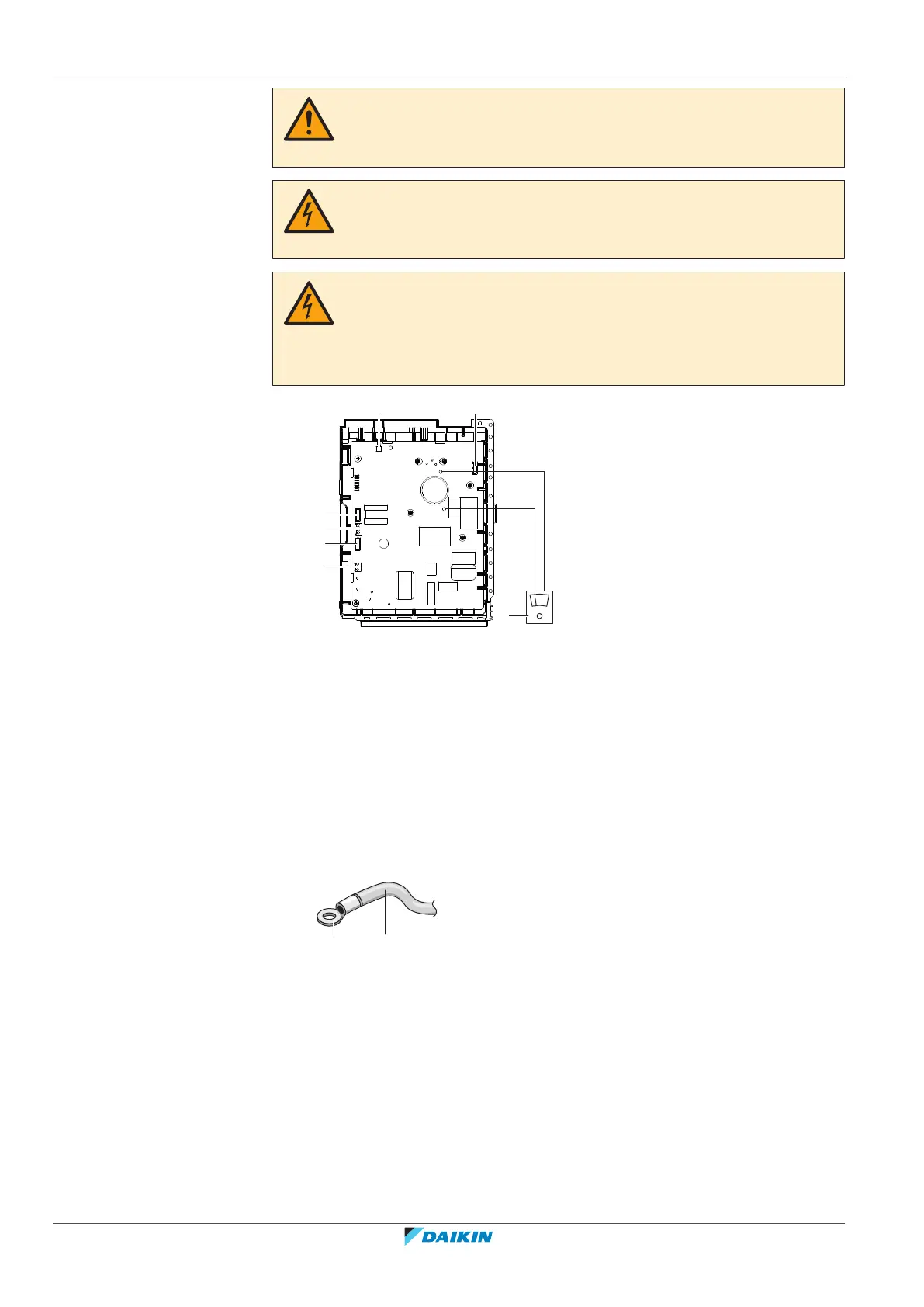
For the location of the terminals, see the wiring diagram.
b
c
DC P1+
DC N1-
a
d
e
g
f
a Multimeter (DC voltage range)
b S80 – reversing solenoid valve lead wire
c S20 – electronic expansion valve lead wire
d S40 – thermal overload relay lead wire
e S90 – thermistor lead wire
f LED
g S70 – fan motor lead wire
6.7.3 Guidelines when connecting the electrical wiring
Keep the following in mind:
▪ If stranded conductor wires are used, install a round crimp-style terminal on the
end of the wire. Place the round crimp-style terminal on the wire up to the
covered part and fasten the terminal with the appropriate tool.
b a
a Stranded conductor wire
b Round crimp-style terminal
▪ Use the following methods for installing wires:
Bekijk gratis de handleiding van Daikin RXM25N2V1B9, stel vragen en lees de antwoorden op veelvoorkomende problemen, of gebruik onze assistent om sneller informatie in de handleiding te vinden of uitleg te krijgen over specifieke functies.
Productinformatie
| Merk | Daikin |
| Model | RXM25N2V1B9 |
| Categorie | Niet gecategoriseerd |
| Taal | Nederlands |
| Grootte | 8936 MB |


