Handleiding
Je bekijkt pagina 25 van 52
13 Piping installation
Installation and operation manual
25
LREN8~12A + LRNUN5A
CO₂ ZEAS outdoor unit and capacity up unit
4P704141-1F – 2024.12
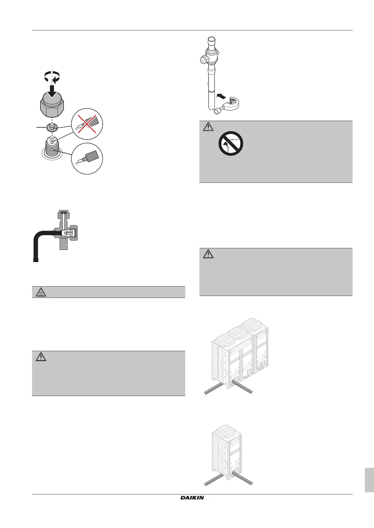
5 Apply screw lock agent or silicon sealant to the screw thread
when mounting the service port cap. Without it, moisture and
condensing water may penetrate and freeze between the screw
thread. As a result, refrigerant may leak and the service port
cap may break.
a
b
a New copper packing
b Screw lock agent or silicon sealant only on screw thread
6 Tighten the service port cap with 2 spanners.
Result: The service port is fully closed.
13.3 Connecting the refrigerant piping
DANGER: RISK OF BURNING/SCALDING
13.3.1 To cut off the spun pipe ends
When the product is shipped, a small amount of refrigerant gas is
kept inside the product. Therefore, the pipes contain a pressure
higher than the atmospheric pressure. For safety reasons, it is
necessary to release the refrigerant before cutting the spun pipe
ends.
WARNING
Any gas or oil remaining inside the stop valve may blow off
the spun piping.
If these instructions are NOT followed correctly it may
result in property damage or personal injury, which may be
serious depending on the circumstances.
1 Make sure the stop valves CsV3 (gas) and CsV4 (liquid) are
open. See "13.2.1To handle the stop valve"[424].
2 In case the outdoor unit is installed indoors: install a pressure
hose to service ports SP3, SP7 and SP11. Check that the
hoses are properly fixed and that they lead outside.
3 Fully open service ports SP3, SP7 and SP11 to release the
refrigerant. See "13.2.3 To handle the service port" [4 24]. All
refrigerant must be evacuated before continuing.
4 Cut off the lower part of the gas and liquid stop valve pipes
along the black line. Always use appropriate tools, such as a
pipe cutter or pair of nippers.
WARNING
NEVER remove the spun piping by brazing.
Any gas or oil remaining inside the stop valve may blow off
the spun piping.
5 Wait until the oil has dripped out of the piping. All oil must be
evacuated before continuing.
6 Close stop valves CsV3 and CsV4 and service ports SP3, SP7
and SP11.
7 Connect the field piping to the cut pipes.
13.3.2 To connect the refrigerant piping to the
outdoor unit
WARNING
ONLY connect the outdoor unit to showcases or blower
coils with a design pressure:
▪ At the high pressure side (liquid side) of 90bar gauge.
▪ At the low pressure side (gas side) of 60bar gauge (is
possible with safety valve at field gas piping).
You can route refrigerant piping to the front or side of the unit.
For the outdoor unit
a
b
a Left side connection
b Front connection
For the capacity up unit
a
b
Bekijk gratis de handleiding van Daikin LRNUN5AY1, stel vragen en lees de antwoorden op veelvoorkomende problemen, of gebruik onze assistent om sneller informatie in de handleiding te vinden of uitleg te krijgen over specifieke functies.
Productinformatie
| Merk | Daikin |
| Model | LRNUN5AY1 |
| Categorie | Koelkast |
| Taal | Nederlands |
| Grootte | 8986 MB |


