Handleiding
Je bekijkt pagina 21 van 52
13 Piping installation
Installation and operation manual
21
LREN8~12A + LRNUN5A
CO₂ ZEAS outdoor unit and capacity up unit
4P704141-1F – 2024.12
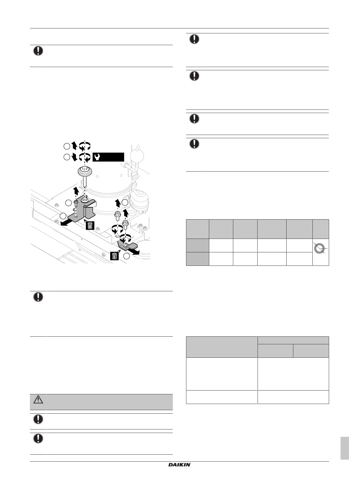
12.3.3 To remove the transportation stay
NOTICE
If the unit is operated with the transportation stay attached,
abnormal vibration or noise may be generated.
The compressor transportation stays protect the unit during
transport. They are located around the middle compressor (INV2).
During installation they must be removed.
1 Loosen the compressor mounting bolt.
2 Remove the screw.
3 Remove and dispose of the transportation stay.
4 Tighten the mounting bolt to 12.3N•m of torque.
5 Remove the 2 screws.
6 Remove and dispose of the transportation stay.
1
4
2
6
3
(12.3 N·m)
5
12.3.4 To provide drainage
Make sure that condensation water can be evacuated properly.
NOTICE
Prepare a water drainage channel around the foundation to
drain waste water from around the unit. When the outdoor
temperatures are negative, the drained water from the
outdoor unit will freeze up. If the water drainage is not
taken care of, the area around the unit might be very
slippery.
13 Piping installation
13.1 Preparing refrigerant piping
13.1.1 Refrigerant piping requirements
WARNING
The unit contains small amounts of refrigerant R744.
NOTICE
Do NOT reuse piping from previous installations.
NOTICE
Foreign materials inside pipes are NOT allowed (including
oils for fabrication).
NOTICE
Refrigerant R744 requires strict cautions for keeping the
system clean and dry. Foreign materials (including mineral
oils or moisture) should be prevented from getting mixed
into the system.
NOTICE
The piping and other pressure-containing parts shall be
suitable for refrigerant and oil. Use K65 (or equivalent)
copper-iron alloy tube system for high-pressure
applications with a working pressure of 90bar gauge at the
refrigeration side.
NOTICE
NEVER use standard hoses and manometers. Use ONLY
equipment that is designed to use with R744.
NOTICE
If the ability to close the stop valves for field piping is
wanted, the installer MUST install a pressure relief valve
on the liquid piping between the outdoor unit and the
refrigeration indoor units.
13.1.2 Refrigerant piping material
Piping material
K65 and equivalent piping, maximum system operation pressure in
field piping is 90bar gauge.
Piping temper grade and thickness
Outer
diameter
(Ø)
Temper
grade
Thickness
(t)
(a)
Design
pressure
Liquid
piping
15.9mm
(5/8")
R300 1.05mm 120 bar
gauge
t
Ø
Gas
piping
22.2mm
(7/8")
R300 1.50mm 120 bar
gauge
(a)
Depending on the applicable legislation and the maximum
working pressure of the unit (see "PS High" on the unit name
plate), larger piping thickness might be required.
13.1.3 Refrigerant piping length and height
difference
Requirements and limits
The piping lengths and height differences must comply with the
following requirements. For an example, see "13.1.4 To select the
piping size"[422].
Requirement Limit
LREN* LREN* +
LRNUN5*
Maximum piping length
Examples:
▪ A+B+C+D+(E or F)
(a)
≤Limit
▪ a+b+c+d+(e or f)
(a)
≤Limit
Low temperature: 100m
(b)
Medium temperature: 130m
(b)
Piping length between LREN*
and LRNUN5*
Not specified, but piping must be
horizontal
Bekijk gratis de handleiding van Daikin LRNUN5AY1, stel vragen en lees de antwoorden op veelvoorkomende problemen, of gebruik onze assistent om sneller informatie in de handleiding te vinden of uitleg te krijgen over specifieke functies.
Productinformatie
| Merk | Daikin |
| Model | LRNUN5AY1 |
| Categorie | Koelkast |
| Taal | Nederlands |
| Grootte | 8986 MB |


