Handleiding
Je bekijkt pagina 13 van 24
12 Unit installation
Installation and operation manual
13
FXSN-B
CO₂ VRV system air conditioner
3P672850-3C – 2024.11
▪ Level. Make sure the unit is level at all four corners using a level
or a water-filled vinyl tube.
b
a
a Water level
b Vinyl tube
NOTICE
Do NOT install the unit tilted. Possible consequence: If
the unit is tilted against the direction of the condensate flow
(the drain piping side is raised), the float switch might
malfunction and cause water to drip.
12.2.2 Guidelines when installing the ducting
CAUTION
▪ Make sure the installation of the duct does NOT exceed
the setting range of the external static pressure for the
unit. Refer to the technical datasheet of your model for
the setting range.
▪ Make sure to install the canvas duct so vibrations are
NOT transmitted to the duct or ceiling. Use a sound-
absorbing material (insulation material) for the lining of
the duct and apply vibration insulation rubber to the
hanging bolts.
▪ When welding, make sure NOT to spatter onto the
drain pan or the air filter.
▪ If the metal duct passes through a metal lath, wire lath
or metal plate of the wooden structure, separate the
duct and wall electrically.
▪ Install the outlet grille in a position where the airflow will
not come into direct contact with people.
▪ Do NOT use booster fans in the duct. Use the function
to adjust the fan rate setting automatically (see
"16Configuration"[418]).
The ducting is to be field supplied.
1 Connect the canvas duct to the inside of the flange on both inlet
and outlet sides. Connect the canvas duct using the accessory
screws.
2 Connect the duct to the canvas duct.
a
b
c b a
ffe ed d
a Screws for duct flanges (accessory)
b Flange (located on the unit)
c Main unit
d Insulation (field supply)
e Canvas duct (field supply)
f Aluminium tape (field supply)
▪ Fixing screws. When installing an air inlet duct, select fixing
screws that stick out 5 mm on the inside of the flange to protect
the air filter from damage during maintenance of the filter.
a
b
c
5 mm
a Air inlet duct
b Inside of the flange
c Fixing screw
3 Wind aluminium tape around the flange and duct connection.
Make sure there are no air leaks at any other connection.
4 Insulate the duct to prevent condensation from forming. Use
glass wool or polyethylene foam 25mm thick.
▪ Filter. Be sure to attach an air filter inside the air passage on the
air inlet side. Use an air filter with dust collecting efficiency ≥50%
(gravimetric method).
12.2.3 Guidelines when installing the drain
piping
Make sure condensation water can be evacuated properly. This
involves:
▪ General guidelines
▪ Connecting the drain piping to the indoor unit
▪ Checking for water leaks
General guidelines
▪ Pipe length. Keep drain piping as short as possible.
▪ Pipe size. Keep the pipe size equal to or greater than that of the
connecting pipe (vinyl pipe of 20 mm nominal diameter and
26mm outer diameter).
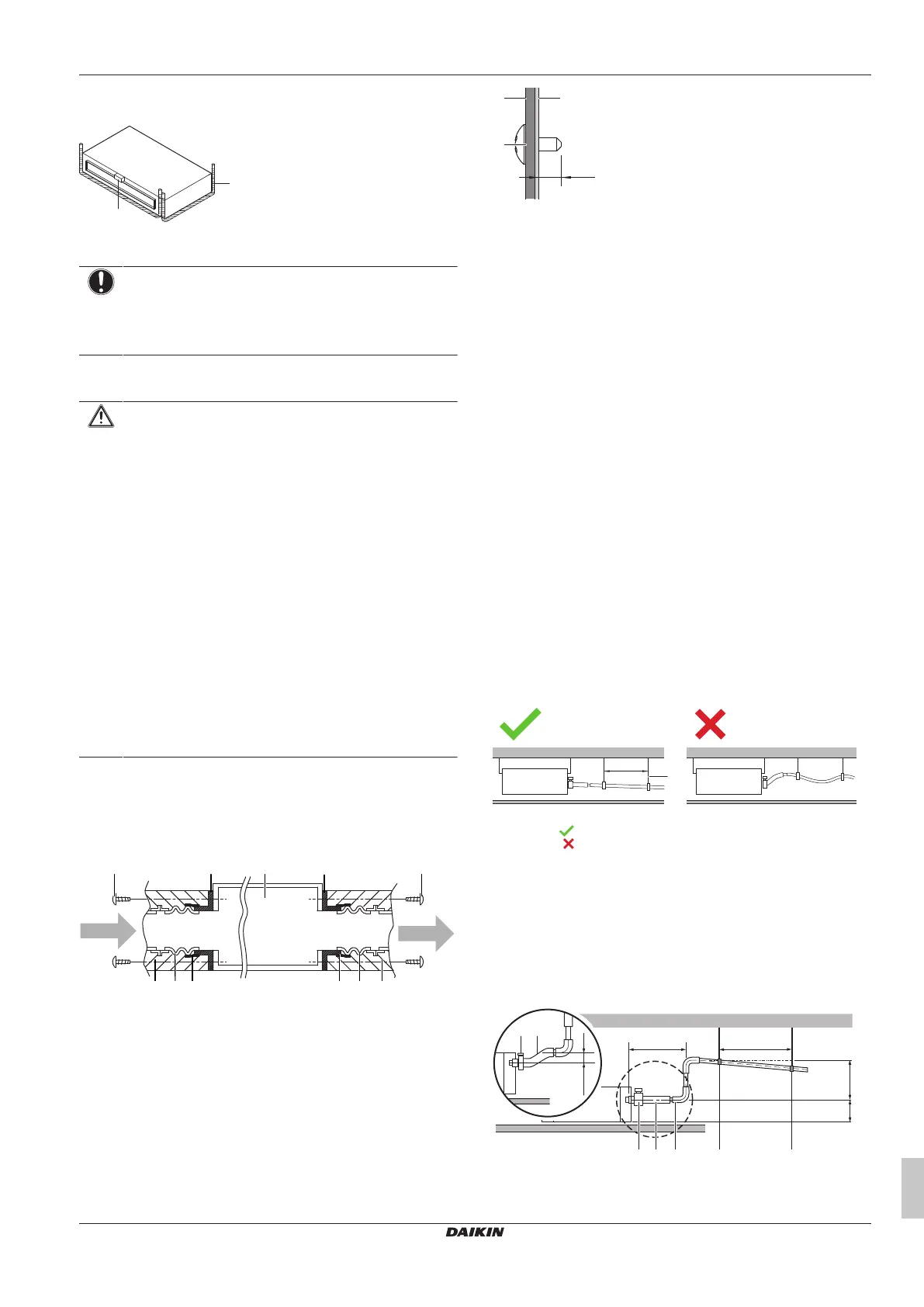
▪ Slope. Make sure the drain piping slopes down (at least 1/100) to
prevent air from being trapped in the piping. Use hanging bars as
shown.
1~1.5 m
a
a Hanging bar
Allowed
Not allowed
▪ Condensation. Take measures against condensation. Insulate
the complete drain piping in the building.
▪ Rising piping. If necessary to make the slope possible, you can
install rising piping.
▪ Drain hose inclination: 0~75 mm to avoid stress on the piping
and to avoid air bubbles.
▪ Rising piping: ≤300 mm from the unit, ≤625 mm perpendicular
to the unit.
≤625
A
≤300
0~75
1000~1500
(mm)
ba
ba ddc
Bekijk gratis de handleiding van Daikin FXSN63B2VEB, stel vragen en lees de antwoorden op veelvoorkomende problemen, of gebruik onze assistent om sneller informatie in de handleiding te vinden of uitleg te krijgen over specifieke functies.
Productinformatie
| Merk | Daikin |
| Model | FXSN63B2VEB |
| Categorie | Airco |
| Taal | Nederlands |
| Grootte | 3884 MB |


