Daikin FXFQ125AVEB handleiding
Handleiding
Je bekijkt pagina 6 van 16
Installation and operation manual
3
1 Select an installation site where the following conditions
are fulfilled and that meets your customer's approval.
• Where optimum air distribution can be ensured.
• Where nothing blocks air passage.
• Where condensate water can be properly drained.
• Where the false ceiling is not noticeably on an incline.
• Where sufficient clearance for maintenance and service can
b
e ensured.
• Where there is no risk of flammable gas leaking.
• The equipment is not intended for use in a potentially explosive
atmosphere.
• Where piping between indoor and outdoor units is possible within the
allowable limit. (Refer to the installation manual of the outdoor unit.)
• This is a class A product. In a domestic environment this product
may cause radio interference in which case the user may be required
to take adequate measures.
• Keep indoor unit, outdoor unit, inter unit wiring and remote controller
at least 1 meter away from televisions and radios. This is to prevent
image interference and noise in those electrical appliances.
(Noise may be generated depending on the conditions under which
the electric wave is generated, even if 1 meter is kept.)
• When installing the wireless remote controller kit, the distance
between wireless remote controller and indoor unit might be shorter
if there are fluorescent lights who are electrically started in the room.
The indoor unit must be installed as far as possible away from
fluorescent lights.
2 Ceiling height
This indoor unit may be installed on ceilings up to 3.5 m in height
(for 125 units: 4.2 m). However, it becomes necessary to make field
settings by the remote controller when installing the unit at a height
over 2.7 m (for 125 units: 3.2 m). Install the unit higher than 2.5 m to
avoid accidental touching.
Refer to "Field setting" on page 8 and to the decoration panel
installation manual.
3 Air flow directions
Select the air flow directions best suited to the room and point of
installation. (For air discharge in 3 directions, it is necessary to
make field settings by means of the remote controller and to close
the air outlet(s). Refer to the installation manual of the optional
blocking pad kit and to "Field setting" on page 8.) (See figure 1 (
= air
flow direction))
4 Use suspension bolts for installation. Check whether the
ceiling is strong enough to support the weight of the
indoor unit. If there is a risk, reinforce the ceiling before
installing the unit.
(The installation pitch is marked on the paper pattern for
installation. Refer to it to check for points requiring
reinforcing.)
Space required for installation see figure 2 ( = air flow
direction)
Preparations before installation
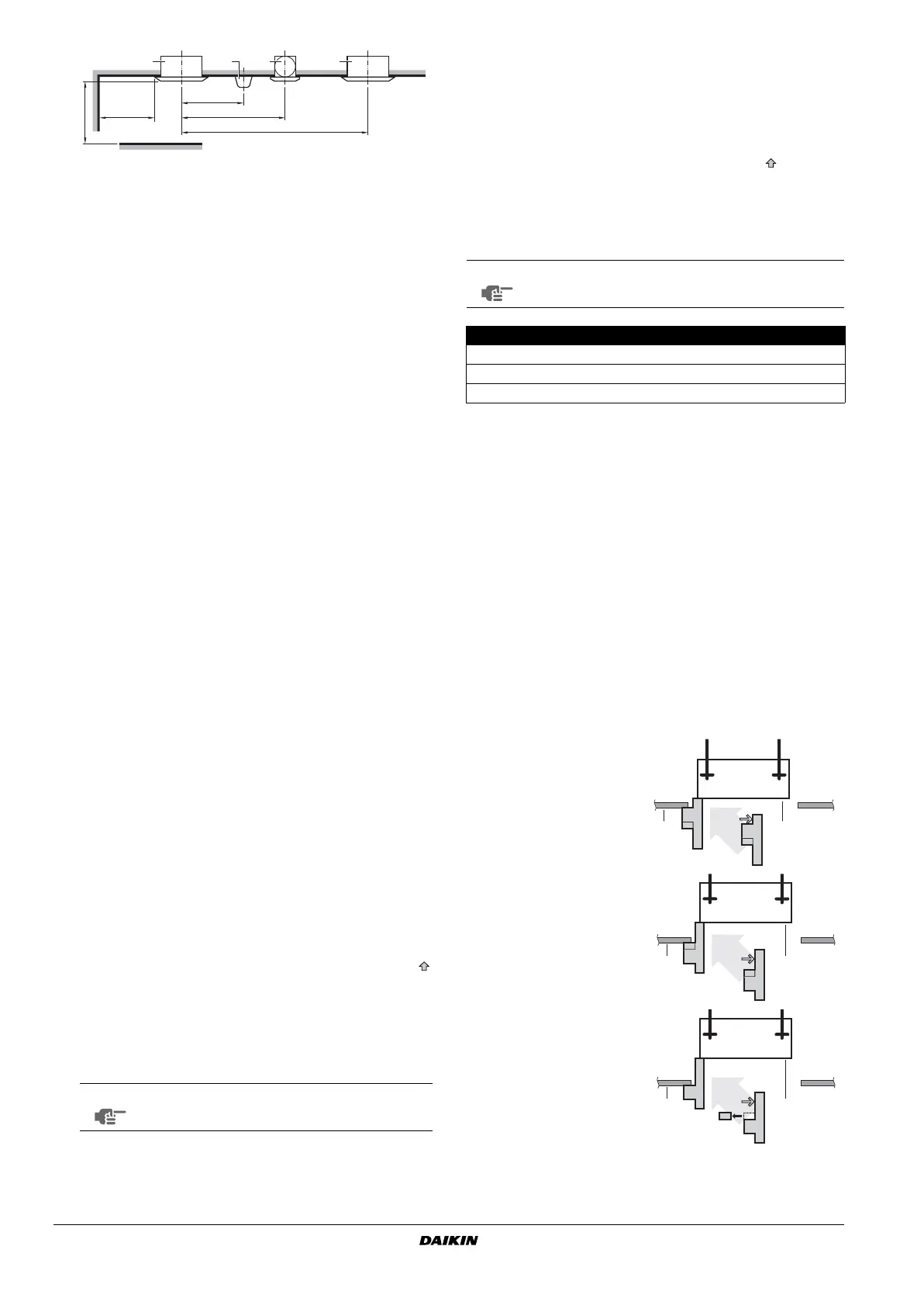
1. Relation of ceiling opening to unit and suspension bolt
position.
(See figure 3)
Use the installation guide (delivered with the unit) for exact
vertical positioning of the unit.
a Indoor unit
b Lighting
The figure describes about a ceiling lighting, but a recessed
ceiling light is not restricted.
c Air fan
A If the air outlet is closed, space marked (A) should be 500 mm at
least. In addition, if both the right and left corner of this air outlet
are closed, space marked (A) should be 200 mm at least.
B ≥1500 mm from any static volume
1 All round air discharge
2 Air discharge in 4 directions
3 Air discharge in 3 directions
NOTE
Air flow directions as shown in figure 1 merely
serve as examples of possible air flow directions.
≥1500 mm
≥
2000 mm
≥
4000 mm
(A)
≥1500 mm
(B)
≥1500 mm
acba
1 Air discharge
2 Air inlet
NOTE
Leave 200 mm or more space where marked with *; on
sides where the air outlet is closed.
Model H
FXFQ20~63 ≥214
FXFQ80+100 ≥256
FXFQ125 ≥298
1
Refrigerant piping
2
Suspension bolt (x4)
3 Hanger bracket
4 False ceiling
5 Suspension bolt pitch
6 Indoor unit
7 Ceiling opening
8 Decoration panel
Apply the short side of the
installation guide in case of
normal installation
Apply the long side of the
installation guide in case of
installation with fresh air
intake kit
Apply the long side of the
installation guide after removal
of the tear-off tab in case of
installation with self
cleaning decoration panel
1 Lower ceiling surface
2 Underside of the unit
1 2
1 2
1 2
EN3P320142-1F.book Page 3 Tuesday, October 3, 2017 2:46 PM
Bekijk gratis de handleiding van Daikin FXFQ125AVEB, stel vragen en lees de antwoorden op veelvoorkomende problemen, of gebruik onze assistent om sneller informatie in de handleiding te vinden of uitleg te krijgen over specifieke functies.
Productinformatie
| Merk | Daikin |
| Model | FXFQ125AVEB |
| Categorie | Niet gecategoriseerd |
| Taal | Nederlands |
| Grootte | 2934 MB |


