Daikin EWWS490VZXSA1 handleiding
Handleiding
Je bekijkt pagina 26 van 67
D-EOMZC00106-17_07EN - 26/67
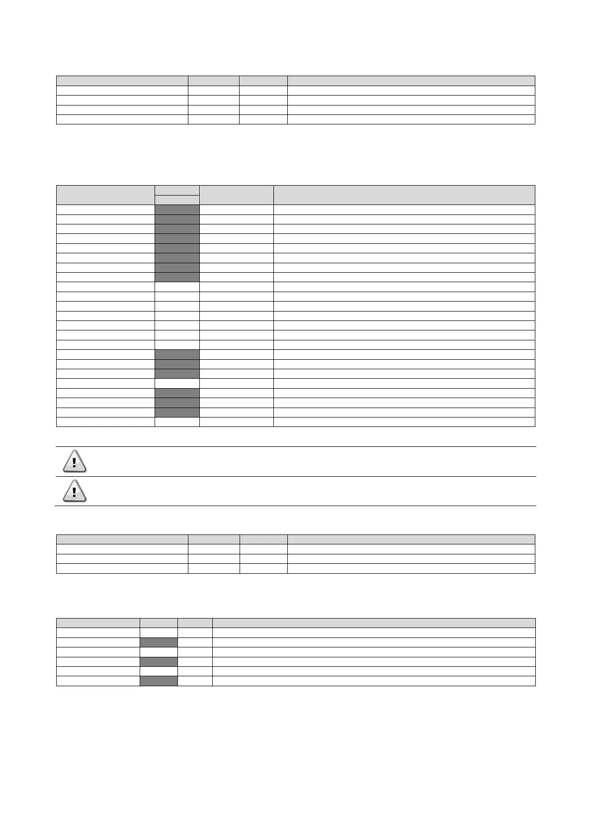
4.12 Commission Unit
Setpoint/Sub-Menu
Default
Range
Description
Alarms Limits
-
Submenu for alarm limits definition
Calibrate Sensors
-
Submenus for Unit and Circuit sensor calibration
Manual Control
-
Submenus for Unit and Circuit manual control
Scheduled Maintenance
-
Submenu for scheduled maintenance
4.12.1 Alarm Limits
This page contains all alarm limits, including low pressure alarm prevention thresholds. In order to ensure proper operation
they have to be set manually according to the specific application.
Setpoint/Sub-Menu
Default
Range
Description
VZ
Low Press Hold=
200.0kPa
0…310.0 kPa
Low pressure safety limit to stop capacity increase (R134a)
Low Press Unld=
190.0kPa
0…250.0 kPa
Low pressure alarm prevention (R134a)
Low Press Hold=
122.0kPa
-27.0…204.0 kPa
Low pressure safety limit to stop capacity increase (R1234ze)
Low Press Unld=
114.0kPa
-27.0…159.0 kPa
Low pressure alarm prevention (R1234ze)
Low Press Hold=
225.0
0.0… 250.0
Low pressure safety limit to stop capacity increase (R513A)
Low Press Unld=
235.0
0.0… 310.0
Low pressure alarm prevention (R513A)
Hi Oil Pr Dly=
30s
10…180s
Delay for the High oil pressure difference alarm
Hi Oil Pr Diff=
250kPa
0.0…415.0kPa
Pressure drop for a clogged filter
Hi Disch Temp=
110.0°C
Maximum discharge temperature limit
Hi Cond Pr Dly=
5s
Delay on the High pressure alarm from transducer
Lo Pr Ratio Dly=
90s
Delay on the low pressure ratio alarm
OAT Lockout=
4.0°C
Air temperature operational limit
Strt Time Lim=
N/A
Time limit for the low ambient start
Evap Flw Proof=
N/A
Flow proof delay
Evp Rec Timeout=
N/A
Recirculating timeout before the alarm is raised
Evap Water Frz=
2.2°C
-18.0…6.0 °C
Freeze protection limit
Water Flw Proof=
15s
5…15s
Flow proof delay
Water Rec Timeout=
3min
1…10min
Recirculating timeout before the alarm is raised
Low DSH Limit=
12.0°C
Minimum acceptable discharge superheat
Gas Conc Lim=
200ppm
Maximum gas concentration limit
HP Sw Test C#1
Off
On, Off. Enables to check operation of the high pressure switch on #1.
HP Sw Test C#2
Off
On, Off. Enables to check operation of the high pressure switch on #2.
Ext Fault Cfg=
N/A
Event, Alarm
Definition of the unit behavior after switching of external alarm contact
The HP Sw Test shuts off all fans while compressor is running in order to raise condenser pressure until tripping
of the high pressure switches. Beware that in case of high pressure switch failure the safety valves will trip and
hot refrigerant will be ejected at high pressure!
Once tripped, the software will get back to normal operation. However, the alarm will not be reset until the high
pressure switches are manually reset through the button included in the switch.
4.12.2 Calibrate Sensors
Setpoint/Sub-Menu
Default
Range
Description
Unit
-
Submenu for Unit calibrate sensor
Circuit #1
-
Submenu for Circuit 1 calibrate sensor
Circuit #2
-
Submenu for Circuit 2 calibrate sensor
4.12.2.1 Unit Calibrate Sensors
This page allows a proper calibration of the unit sensors.
Setpoint/Sub-Menu
Default
Range
Description
Evap LWT=
7.0°C
Evaporator LWT current reading (includes the offset)
Evp LWT Offset=
0.0°C
Evaporator LWT calibration
Evap EWT=
12.0°C
Evaporator EWT current reading (includes the offset)
Evp EWT Offset=
0.0°C
Evaporator EWT calibration
Outside Air=
35.0°C
Outside Air Temperature current reading (includes the offset)
OAT Offset=
0.0°C
Outside Air Temperature calibration
Bekijk gratis de handleiding van Daikin EWWS490VZXSA1, stel vragen en lees de antwoorden op veelvoorkomende problemen, of gebruik onze assistent om sneller informatie in de handleiding te vinden of uitleg te krijgen over specifieke functies.
Productinformatie
| Merk | Daikin |
| Model | EWWS490VZXSA1 |
| Categorie | Niet gecategoriseerd |
| Taal | Nederlands |
| Grootte | 9055 MB |


