Handleiding
Je bekijkt pagina 81 van 84
Air cooled inverter water chiller
OPERATION
MANUAL
EWAD TZ B 160-700
Air cooled inverter water chiller
D-EOMAC00909-16EN
Operation Manual
81
7 Options
7.1 Total Heat Recovery (Optional)
This chiller can handle a total heat recovery option. This feature will require an additional module
and sensors to read the entering and leaving heat recovery water temperatures, command a heat
recovery water pump.
The heat recovery is enabled through the Q8 switch installed on the unit and requires to adjust
settings on the unit controller in order to make it work as needed. First of all the function needs to
be enabled on the main controller in order to display all the settings related to this function. With
reference to section 4.3.5 the heat recovery enable setpoint has to be chanded to Enable.
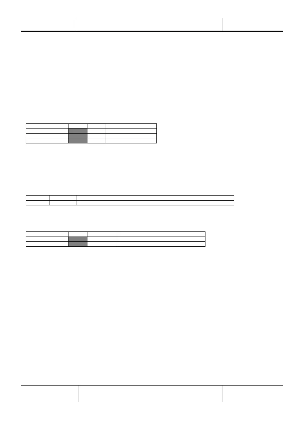
Setpoint/Sub-Menu
Default
Range
Description
Apply Changes=
No
No, Yes
C1 # Of Fans=
6
Number of fans available.
Heat Recovery=
Enable
Disable, Enable
When this is done the controller will need to be reset by applying the changes.
After the reboot all the heat recovery data and settings will be displayed on the HMI. In the
View/Set Unit – Temperatures the heat recovery entering and leaving water temperatures will be
then visible.
HR LWT=
-273.1°C
Heat Recovery Leaving Water Temperature (displayed only if Heat Recovery set on)
HR EWT=
-273.1°C
Heat Recovery Entering Water Temperature (displayed only if Heat Recovery set on)
Additionally the Heat Recovery setpoint and differential will become visible and can be adjusted as
needed:
Setpoint/Sub-Menu
Default
Range
Description
HR EWT Stp
40.0°C
30.0…50.0°C
Heat Recovery Entering Water Setpoint
HR EWT Dif
2.0°C
1.0…10.0°C
Heat Recovery Water Temperature differential
7.2 Energy Meter including Current Limit (Optional)
An energy meter can be optionally installed on the unit. The energy meter is connected through
Modbus to the unit controller, which can display all relevant electrical data such as:
Line to Line Voltage (per phase and average)
Line Current (per phase and average)
Active Power
Cos Phi
Active Energy
More details are described in chapter 4.2.10. All these data can be also accessed from a BMS by
connecting it to a communication module. See the communication module manual for details on
the device and parameter settings.
Both the energy meter device and the unit controller need to be properly set. The instructions
below detail how to set the energy meter. Refer to the specific instructions of the energy meter for
more detail on the operation of the device.
Bekijk gratis de handleiding van Daikin EWAD620TZPLB, stel vragen en lees de antwoorden op veelvoorkomende problemen, of gebruik onze assistent om sneller informatie in de handleiding te vinden of uitleg te krijgen over specifieke functies.
Productinformatie
| Merk | Daikin |
| Model | EWAD620TZPLB |
| Categorie | Airco |
| Taal | Nederlands |
| Grootte | 11976 MB |


