Handleiding
Je bekijkt pagina 6 van 28
Installation and operation manual
3
EUWY(*)5~24KBZW1
Packaged reversible air to water heat pumps
4PW61655-1 – 07.2010
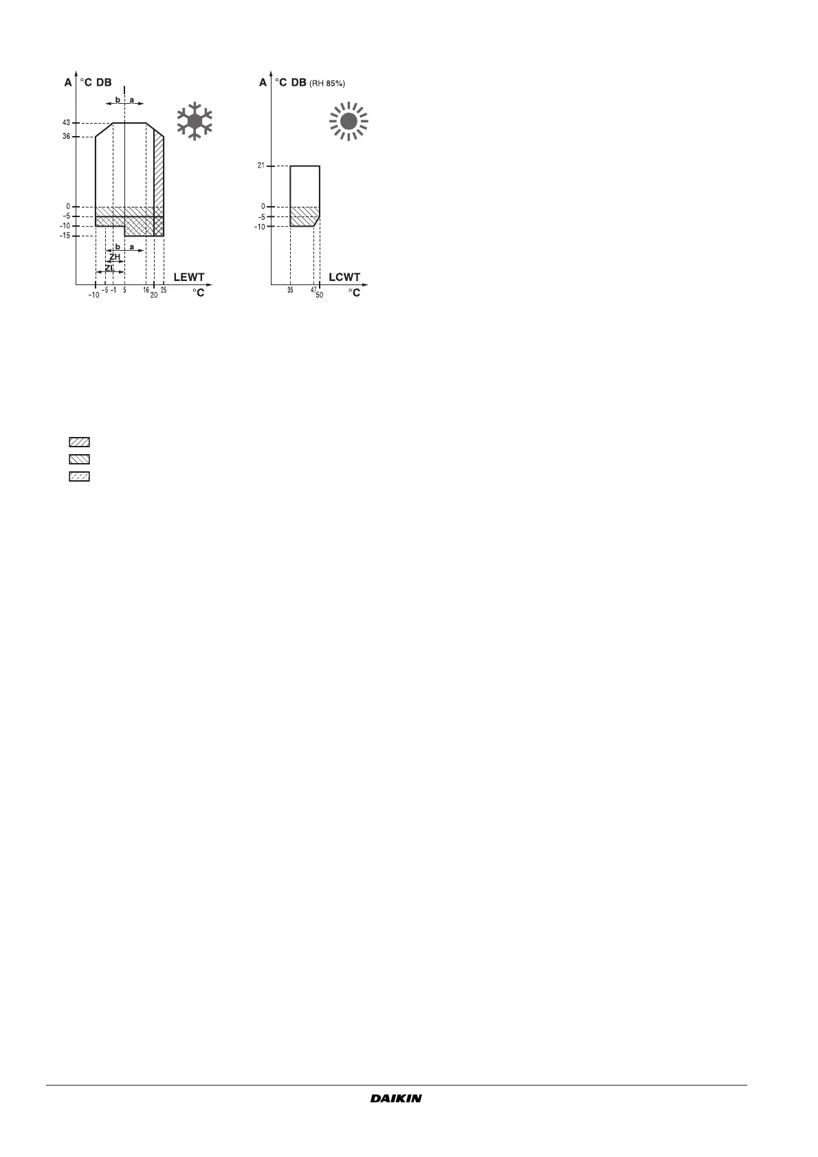
Operation range
Main components
(See figure 1)
Displayed unit = EUWYB12KBZW1.
1 Condenser (cooling mode) or evaporator (heating mode)
The function of the condenser is to change the state of the
refrigerant from gaseous to liquid. The heat gained by the gas in
the evaporator is discharged through the condenser to the
ambient air, and the vapour condenses to liquid.
2 Compressor
The compressor acts as a pump and circulates the refrigerant in
the refrigeration circuit. It compresses the refrigerant vapour
coming from the evaporator at the pressure at which it can easily
be liquefied in the condenser.
3 Bi-directional flow refrigerant filter
The filter installed behind the condenser removes small particles
from the refrigerant to prevent blockage of the tubes.
4 Bi-directional flow expansion valve
The liquid refrigerant coming from the condenser enters the
evaporator via an expansion valve. The expansion valve brings
the liquid refrigerant to a pressure at which it can easily be
evaporated in the evaporator.
5 Evaporator (cooling mode) or condenser (heating mode)
The main function of the evaporator is to take heat from the
water that flows through it. This is done by turning the liquid
refrigerant, coming from the condenser, into gaseous
refrigerant.
6 Pressure port refrigerant circuit
These ports make it possible to measure refrigerant pressure in
the pipes.
7 Charge valve
Allows refrigerant charge in the circuit.
8 Water in/outlet connection
The water inlet and outlet connection allow an easy connection
of the unit to the water circuit of the air handling unit or industrial
equipment.
9 Pump (only EUWYP, EUWYB)
The pump circulates the water in the circuit.
10 Pressure regulating valve
The pressure regulating valve is used to regulate the water flow
in the system.
11 Expansion vessel (only EUWYP, EUWYB)
The water in the water circuit expands with rising temperatures.
The expansion vessel stabilizes the pressure changes with
changing water temperatures by giving free space to the
changing water volume.
12 Buffer tank (only EUWYB)
The buffer tank reduces the variation in water temperature in the
water circuit. This prevents frequent compressor starts and
stops.
13 Drain valve
The drain valve permits complete drainage of the chiller water
system during maintenance or in case of shut down.
14 Fill valve (only EUWYP, EUWYB)
The water circuit can be filled with water via this fill valve.
15 Air purge valve
Remaining air in the chiller water system will be automatically
removed via the air purge valve.
16 Pressure ports water circuit
It is possible to detect any blockage in the water circuit or a
malfunction of the pump by means of the 3 pressure ports.
U 7/16 flare pressure ports are provided to connect a device for
measuring the pump pressure and the evaporator pressure
drop. The waterflow can be deducted from these pressures
(Refer to "Figures pressure characteristics" on page 10).
17 Water filter
The filter installed in front of the pump removes dirt from the
water to prevent damage to the pump or blockage of the
evaporator. The water filter should be cleaned on a regular base.
18 Ball valve
A ball valve is installed in front of and behind the water filter to
allow filter cleaning without having to drain the water circuit.
19 Manometer
The manometer allows readout of available water pressure to
load.
20 Sensor for inlet water temperature
The measured inlet water temperature is used by the controller
for regulating the outlet water temprature.
21 High pressure gauge (optional)
Measurement on high pressure side compressor.
22 Low pressure gauge (optional)
Measurement on low pressure side compressor.
23 Liquid receiver
The liquid receiver makes sure to only have liquid refrigerant
before expansion into evaporator.
24 Accumulator
The accumulator makes sure to only have gaseous refrigerant
before compression.
25 4-way valve
The 4-way valve reverses the refrigerant flow in the unit to
change from cooling mode to heating mode.
26 Defrost sensor
The defrost sensor measures the temperature of the air heat
exchanger when the unit is working in heating mode. If the
temperature becomes too low, the unit will defrost until the
temperature of the air heat exchanger reaches an acceptable
level.
A
Outdoor temperature
a
Standard (water)
b
Option (glycol)
°C DB
°C dry bulb
LEWT
Leaving evaporator water temperature
LCWT
Leaving condenser water temperature
RH
Relative humidity
Pull down operation area
Protect the water circuit against freezing.
When the units operate below –5°C and are installed in a
rather windy region, a windscreen is required.
Bekijk gratis de handleiding van Daikin EUWY-KBZW1, stel vragen en lees de antwoorden op veelvoorkomende problemen, of gebruik onze assistent om sneller informatie in de handleiding te vinden of uitleg te krijgen over specifieke functies.
Productinformatie
| Merk | Daikin |
| Model | EUWY-KBZW1 |
| Categorie | Airco |
| Taal | Nederlands |
| Grootte | 4504 MB |


