Daikin ERA250AMYFB handleiding
Handleiding
Je bekijkt pagina 35 van 48
17 Electrical installation
Installation and operation manual
35
ERA200~300AMYFB
Inverter outdoor unit for AHU option kit and air curtains
4P780153-1 – 2024.07
5 Route the cables through the frame according to the illustration
below.
Note: for ERA200, choose one of the two possibilities to route the
cables through the frame.
a
b
a
b
2
1
a
b
ERA200
ERA250+300
a Interconnection cable
b Power supply cable
6 Remove the selected knockout holes by tapping on the
attachment points with a flat head screwdriver and a hammer.
7 Install a cable protection in the knockout hole:
▪ It is recommended to install a PG type cable gland in the
knockout hole.
▪ When you do not use a cable gland, protect the cables with
vinyl tubes to prevent the edge of the knockout hole from
cutting the wires:
a b
A B
c d e
A Inside of the outdoor unit
B Outside of the outdoor unit
a Cable
b Bush
c Nut
d Frame
e Tube
8 Route the cables out of the unit.
9 Reattach the service cover. See "14.2.2 To close the outdoor
unit"[425].
10 Connect an earth leakage circuit breaker and fuse to the power
supply line as specified in "17.2 Specifications of standard
wiring components"[433].
17.5 To connect the external outputs
SVS and SVEO output
The SVS and SVEO outputs are contacts on terminal X2M.
The SVS output is a contact on terminal X2M that closes in case a
leak is detected, failure or disconnection of the R32 sensor (located
in the indoor unit).
The SVEO output is a contact on terminal X2M that closes in case of
occurrence of general errors. See "8.1Error codes: Overview"[413]
and "22.1.1 Error codes: Overview" [4 42] for errors that will trigger
this output.
Outdoor output connection requirements
Voltage 220~240V
Maximum current 0.5A
Wire size Only use harmonised wiring providing double
insulation and suitable for the applicable
voltage.
2-core cable
Minimum cable section of 0.75mm²
NOTICE
Do NOT use the outputs as a power source. Instead, use
each output to energize a relay that controls the external
circuit.
WHT
SVEO SVS
BLK GRY PPL
ba
c
X2M
a SVEO output terminals (1 and 2)
b SVS output terminals (1 and 2)
c Cable to SVS output device (example)
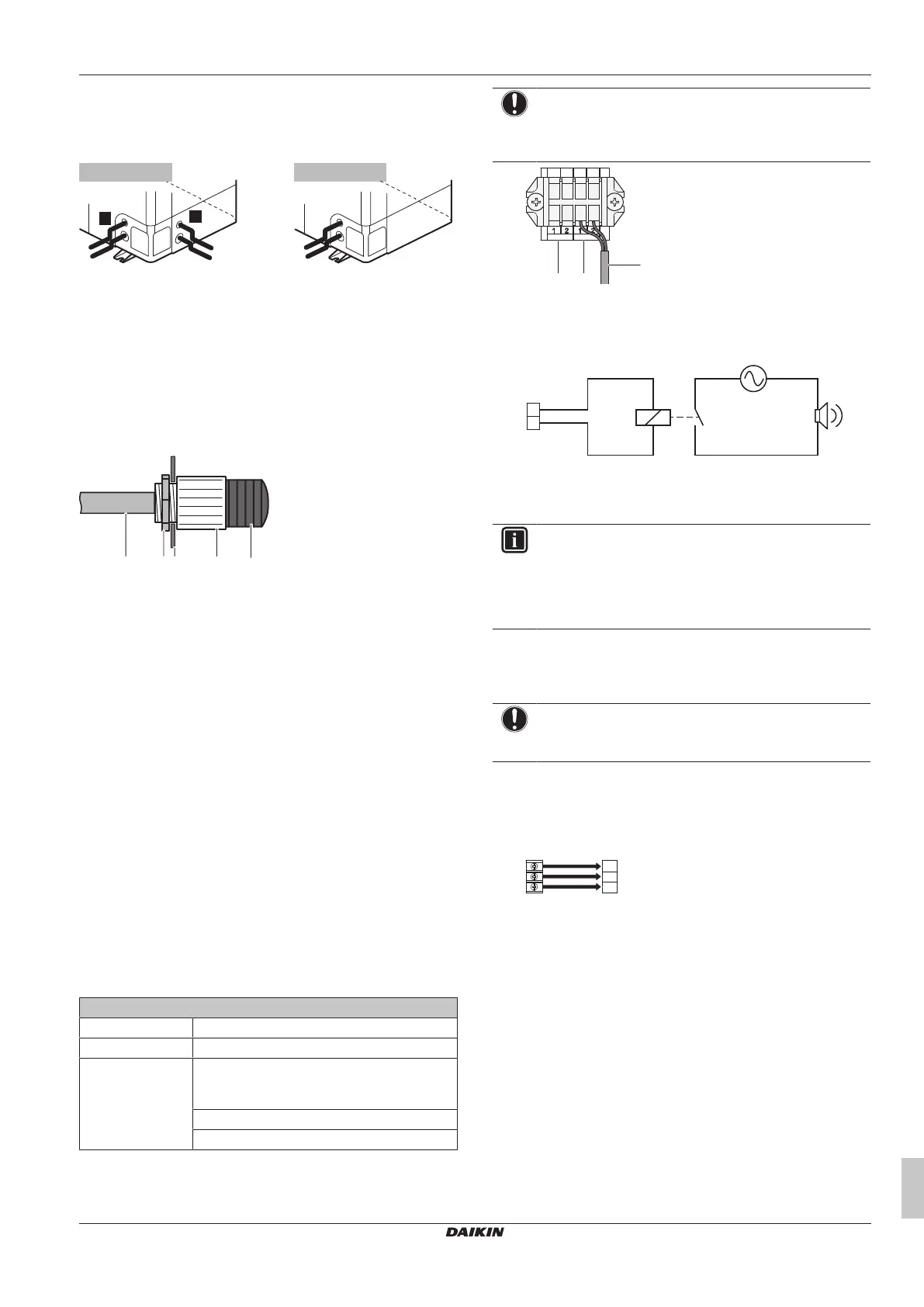
Example:
X2M
(SVS)
a
1
2
c
b d
a SVS output terminal
b Relay
c AC power supply 220~240VAC
d External alarm
INFORMATION
Sound data about the refrigerant leakage alarm are
available in the technical data sheet of the user interface.
E.g. the BRC1H52* controller generates an alarm of 65dB
(sound pressure, measured at 1 m distance from the
alarm).
17.6 To connect the cool/heat selector
switch option
NOTICE
Do NOT use the cool/heat selector switch in case the T3T4
input is used.
In order to control the cooling or heating operation from a central
location, the following optional cool/heat selector switch
(KRC19-26A) can be connected:
1 Connect the cool/heat selector switch to terminal X1M of the
cool/heat selector PCB.
KRC19-26A
1
2
3
A
B
C
X1M
X1M Terminal on the PCB
KRC19-26A Cool/heat selector switch
2 Route the wires in the switchbox as shown:
Bekijk gratis de handleiding van Daikin ERA250AMYFB, stel vragen en lees de antwoorden op veelvoorkomende problemen, of gebruik onze assistent om sneller informatie in de handleiding te vinden of uitleg te krijgen over specifieke functies.
Productinformatie
| Merk | Daikin |
| Model | ERA250AMYFB |
| Categorie | Ventilator |
| Taal | Nederlands |
| Grootte | 8144 MB |


