Daikin ERA250AMYFB handleiding
Handleiding
Je bekijkt pagina 34 van 48
17 Electrical installation
Installation and operation manual
34
ERA200~300AMYFB
Inverter outdoor unit for AHU option kit and air curtains
4P780153-1 – 2024.07
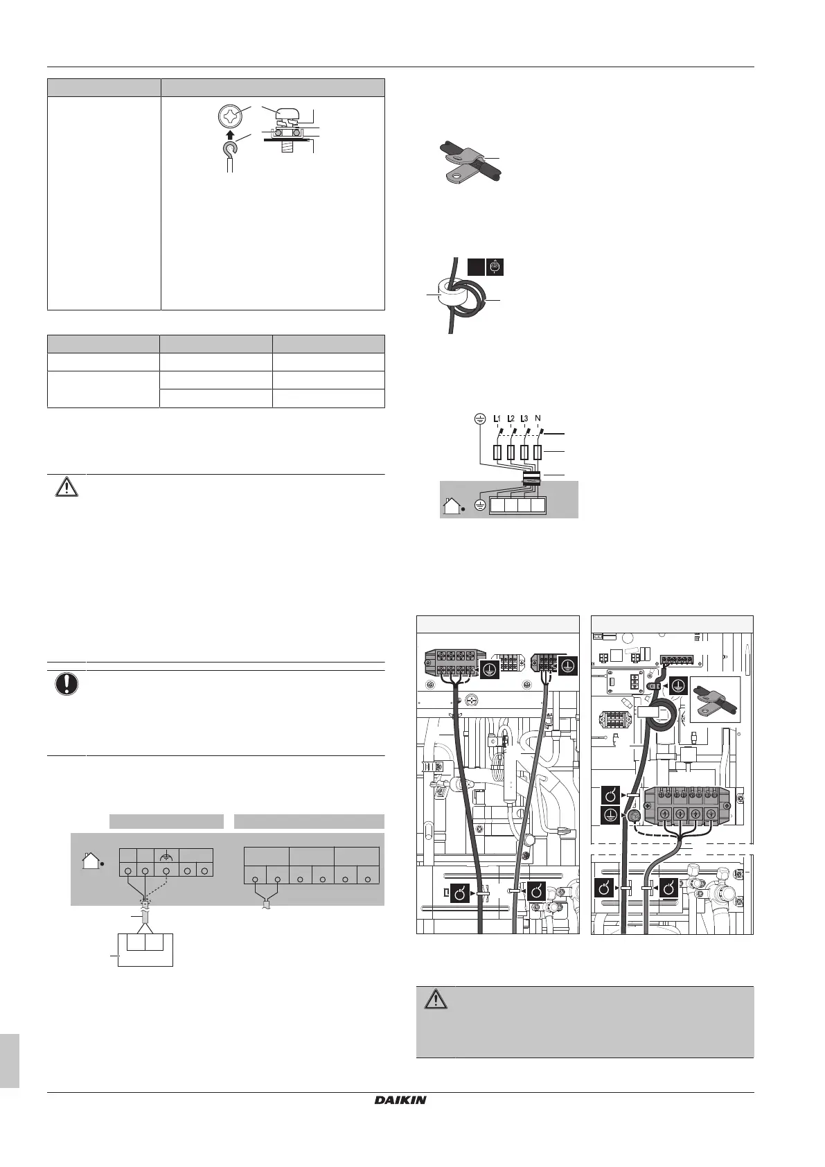
Wire type Installation method
Single-core wire
Or
Stranded conductor
wire twisted to "solid-
like" connection
d
a
b c
f
e
a Clockwise curled wire (single-core or
twisted stranded conductor wire)
b Screw
c Spring washer
d Flat washer
e Coupling washer
f Sheet metal
Tightening torques
Wiring Screw size Tightening torque
Transmission wiring M3.5 0.8~0.97N•m
Power supply wiring ERA200 : M5 2.2~2.7N•m
ERA250+300 : M8 5.5~7.3N•m
17.4 To connect the electrical wiring to
the outdoor unit
CAUTION
▪ When connecting the power supply: connect the earth
cable first, before making the current-carrying
connections.
▪ When disconnecting the power supply: disconnect the
current-carrying cables first, before separating the earth
connection.
▪ The length of the conductors between the power supply
stress relief and the terminal block itself MUST be as
such that the current-carrying wires are tautened before
the earth wire is in case the power supply is pulled
loose from the stress relief.
NOTICE
▪ Follow the wiring diagram (delivered with the unit,
located at the inside of the service cover).
▪ Make sure the electrical wiring does NOT obstruct
proper reattachment of the service cover.
1 Remove the service cover. See "14.2.1 To open the outdoor
unit"[424].
2 Connect the transmission wiring as follows:
ERA200 ERA250+300
X1M (A1P)
F1 F2 SFB
a
X3M
F1 Q2F2F1 Q1F2
TO MULTI
UNIT
TO OUT/DTO IN/D
F1 F2
b
a Use the conductor of sheathed wire (2wire) (no polarity)
b Terminal board (field supply)
Note: The indoor F1/F2 interconnection cable MUST be shielded:
▪ ERA200 : the shielding is earthed (only at outdoor unit side of the
cable) via the middle screw on the terminal X3M.
▪ ERA250+300 : the shielding is earthed (only at outdoor unit side
of the cable) via a metal P-clamp. Strip the insulation up to the
shielding mesh, to provide full contact of the earth with the
shielding. See illustration below:
a
a P-clamp for cable shield earthing
Note: For ERA250+300 , the interconnection cable MUST pass
through the ferrite core 3 times (3 passes, 2turns). See illustration
below:
3×
b
a
a Interconnection cable
b Ferrite core
3 Connect the power supply as follows:
3N~ 50
/
60
Hz
380-415
/
400
V
L1 L2 L3
L1 L2 L3
N
X1M
a
b
c
a Earth leakage circuit breaker
b Fuse
c Power supply cable
4 Fix the cables (power supply and interconnection cable) with a
cable tie to the stop valve attachment plate and route the wiring
according to the illustration below.
c
a
b
a
b
c
c
X1M
X1M
X3M
X1M (A1P)
ERA200 ERA250+300
a Interconnection cable
b Power supply cable
c Cable tie
WARNING
Do NOT strip the outer cable jacket lower than the fixation
point on the stop valve attachment plate.
Bekijk gratis de handleiding van Daikin ERA250AMYFB, stel vragen en lees de antwoorden op veelvoorkomende problemen, of gebruik onze assistent om sneller informatie in de handleiding te vinden of uitleg te krijgen over specifieke functies.
Productinformatie
| Merk | Daikin |
| Model | ERA250AMYFB |
| Categorie | Ventilator |
| Taal | Nederlands |
| Grootte | 8144 MB |


