Daikin ERA200AMYFB handleiding
Handleiding
Je bekijkt pagina 46 van 48
24 Technical data
Installation and operation manual
46
ERA200~300AMYFB
Inverter outdoor unit for AHU option kit and air curtains
4P780153-1 – 2024.07
j Capillary tube (2×)
k Charge port
l Heat sink
M1C Compressor
M1F-M2F Fan motor
R1T Thermistor (air)
R3T Thermistor (suction accumulator)
R4T Thermistor (heat exchanger, liquid)
R5T Thermistor (liquid)
R6T Thermistor (subcool heat exchanger, gas)
R7T Thermistor (de-icer)
R8T Thermistor (M1C body)
R21T Thermistor (M1C discharge pipe)
S1NPH High pressure sensor
S1NPL Low pressure sensor
S1PH High pressure switch
Y1E Electronic expansion valve (main)
Y2E Electronic expansion valve (subcool heat exchanger)
Y3E Electronic expansion valve (inverter cooling)
Y4E Electronic expansion valve (liquid injection)
Y1S Solenoid valve (4-way valve)
Y2S Solenoid valve (accumulator oil return)
Cooling
Heating
24.3 Wiring diagram: Outdoor unit
The wiring diagram is delivered with the unit, located at the inside of
the service cover.
Notes:
1 Symbols (see below).
2 Refer to the installation or service manual on how to use the
BS1~BS3 push buttons and DS1~DS2 switches.
3 Do not operate the unit by short-circuiting protection device
S1PH.
4 Refer to the installation manual for indoor-outdoor
transmission F1-F2 wiring.
5 When using the central control system, connect outdoor-
outdoor transmission F1-F2.
6 The capacity of the contact is 220~240VAC – 0.5A. (Rush
current needs 3A or less)
7 Use dry contact for micro-current (1mA or less 12VDC).
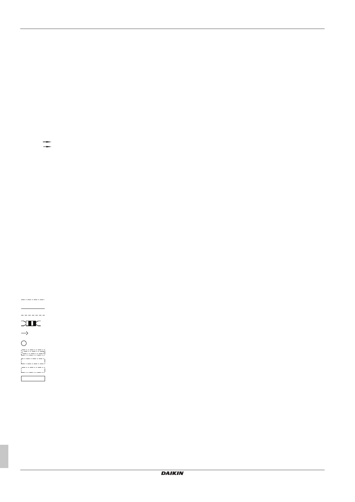
Symbols:
X1M Main terminal
Earth wiring
15
Wire number 15
Field wire
Field cable
**
/12.2
Connection ** continues on page 12 column 2
1
Several wiring possibilities
Option
Not mounted in switch box
Wiring depending on model
PCB
Colours:
BLK Black
BLU Blue
BRN Brown
GRN Green
ORG Orange
RED Red
WHT White
YLW Yellow
Legend for wiring diagram:
A1P Printed circuit board (main)
A2P Printed circuit board (noise filter)
A3P Printed circuit board (inverter)
A4P Printed circuit board (fan 1)
A5P Printed circuit board (fan 2)
A6P Printed circuit board (cool/heat selector)
BS* (A1P) Push button switch
DS* (A1P) DIP switch
E1HC Crankcase heater
F1U (A1P) Fuse (T 10A / 250V)
F1U, F2U Fuse (T 1A / 250V)
F3U Field fuse (field supply)
HAP (A1P) Light-emitting diode (service monitor is green)
K*R (A*P) Relay on PCB
L1R Reactor
M1C Motor (compressor)
M1F, M2F Motor (upper and lower fan)
Q1DI Earth leakage circuit breaker (field supply)
R1T Thermistor (air)
R3T Thermistor (suction accumulator)
R4T Thermistor (heat exchanger liquid)
R5T Thermistor (liquid)
R6T Thermistor (subcool heat exchanger gas)
R7T Thermistor (de-icer)
R8T Thermistor (M1C body)
R21T Thermistor (M1C discharge pipe)
S1NPH High pressure sensor
S1NPL Low pressure sensor
S1PH High pressure switch
S1S Air control switch (optional)
S2S Cool/heat switch (optional)
SEG* (A1P) 7-segment display
SFB Mechanical ventilation error input (field supply)
T1A Current sensor
X*A Connector
X*M Terminal strip
Y1E Electronic expansion valve (heat exchanger)
Y2E Electronic expansion valve (subcool heat exchanger)
Y3E Electronic expansion valve (inverter cooling)
Y4E Electronic expansion valve (liquid injection)
Y1S Solenoid valve (4‑way valve)
Y2S Solenoid valve (accumulator oil return)
Y3S Error operation output (SVEO)(field supply)
Y4S Leak sensor output (SVS)(field supply)
Z*C Noise filter (ferrite core)
Bekijk gratis de handleiding van Daikin ERA200AMYFB, stel vragen en lees de antwoorden op veelvoorkomende problemen, of gebruik onze assistent om sneller informatie in de handleiding te vinden of uitleg te krijgen over specifieke functies.
Productinformatie
| Merk | Daikin |
| Model | ERA200AMYFB |
| Categorie | Ventilator |
| Taal | Nederlands |
| Grootte | 8144 MB |


