Daikin ERA200AMYFB handleiding
Handleiding
Je bekijkt pagina 45 van 48
24 Technical data
Installation and operation manual
45
ERA200~300AMYFB
Inverter outdoor unit for AHU option kit and air curtains
4P780153-1 – 2024.07
24.1 Service space: Outdoor unit
When mounting units side by side, the piping route must be to the
front or downwards. In this case the piping route to the side is not
possible.
Single unit ( ) | Single row of units ( )
→ See "figure1"[42] on the inside of the front cover of this manual.
A,B,C,D Obstacles (walls/baffle plates)
E Obstacle (roof)
a,b,c,d,e Minimum service space between the unit and obstacles
A, B, C, D and E
e
B
Maximum distance between the unit and the edge of
obstacle E, in the direction of obstacle B
e
D
Maximum distance between the unit and the edge of
obstacle E, in the direction of obstacle D
H
U
Height of the unit
H
B
,H
D
Height of obstacles B and D
1 Seal the bottom of the installation frame to prevent
discharged air from flowing back to the suction side
through the bottom of the unit.
2 Maximum two units can be installed.
Not allowed
Note: For better serviceability, use a distance ≥250 mm for all
dimensions marked with 'a'.
Multiple rows of units ( )
→ See "figure2"[42] on the inside of the front cover of this manual.
Note: For better serviceability, use a side by side distance ≥250mm
(instead of ≥100mm as shown on the figures above).
Stacked units (max. 2 levels) ( )
→ See "figure3"[42] on the inside of the front cover of this manual.
A1=>A2 (A1) If there is danger of drainage dripping and freezing
between the upper and lower units…
(A2) Then install a roof between the upper and lower
units. Install the upper unit high enough above the lower
unit to prevent ice buildup at the upper unit's bottom
plate.
B1=>B2 (B1) If there is no danger of drainage dripping and
freezing between the upper and lower units…
(B2) Then it is not required to install a roof, but seal the
gap between the upper and lower units to prevent
discharged air from flowing back to the suction side
through the bottom of the unit.
Note: For better serviceability, use a side by side distance ≥250mm
(instead of ≥100mm as shown on the figures above).
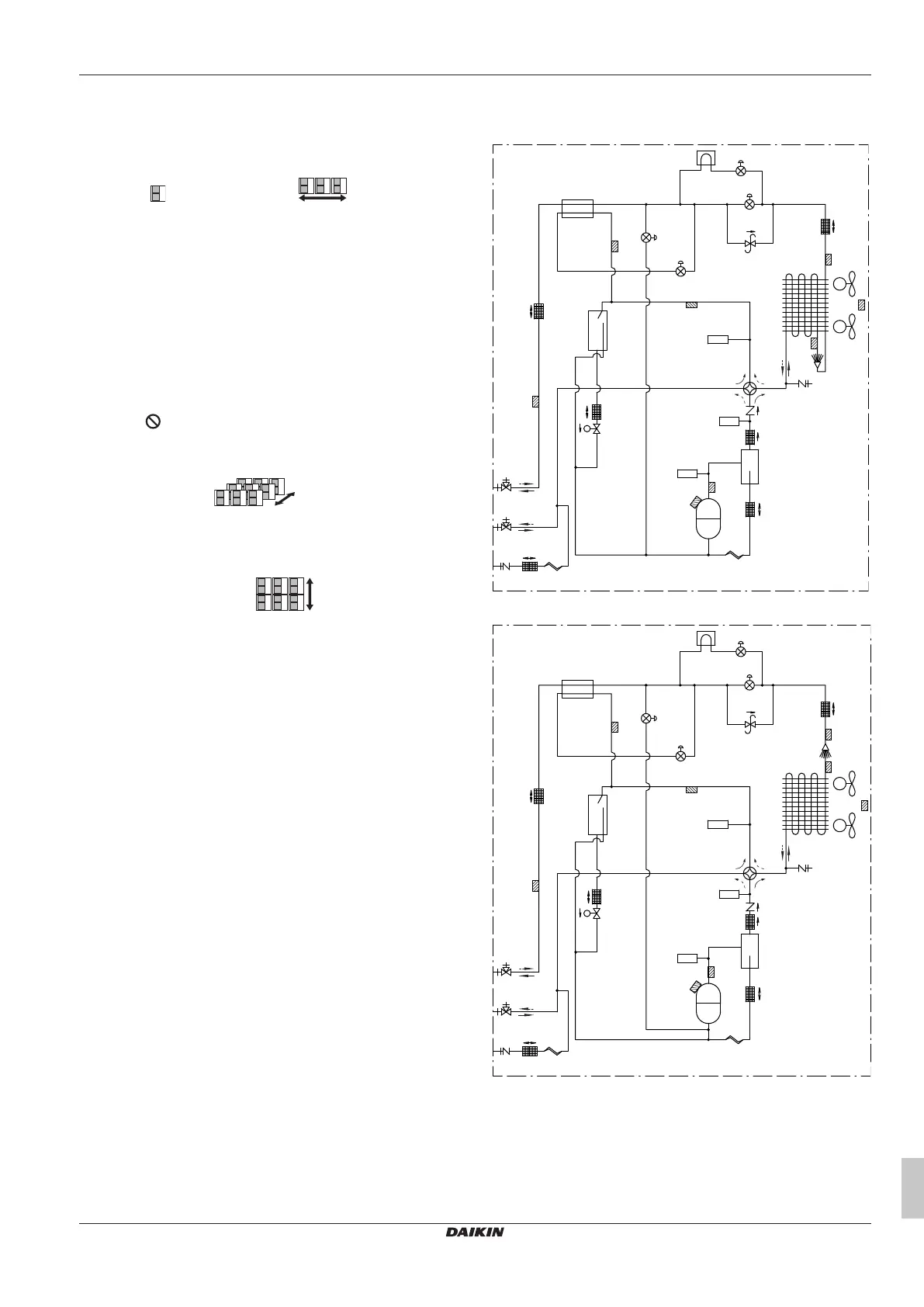
24.2 Piping diagram: Outdoor unit
Piping diagram: ERA200
k
c
d
e
f
l
h
i
Y2S
S1NPL
S1PH
R1T
g
M1F
M2F
R4T
R6T
R7T
a
b
Y3E
Y1E
Y2E
Y4E
Y1S
S1NPH
INV
M1C
R8T
R5T
R3T
R21T
j
j
Piping diagram: ERA250+300
k
c
d
e
f
h
i
Y2S
S1PH
R1T
g
M1F
M2F
R4T
R7T
R6T
a
b
Y3E
Y1E
Y2E
Y4E
Y1S
S1NPH
INV
M1C
R5T
j
j
R8T
R21T
S1NPL
R3T
l
Legend:
a Stop valve (gas)
b Stop valve (liquid)
c Filter (6×)
d Accumulator
e Subcool tube heat exchanger
f Pressure regulating valve
g Heat exchanger
h Service port
i Oil separator
Bekijk gratis de handleiding van Daikin ERA200AMYFB, stel vragen en lees de antwoorden op veelvoorkomende problemen, of gebruik onze assistent om sneller informatie in de handleiding te vinden of uitleg te krijgen over specifieke functies.
Productinformatie
| Merk | Daikin |
| Model | ERA200AMYFB |
| Categorie | Ventilator |
| Taal | Nederlands |
| Grootte | 8144 MB |


