Daikin DSR1 handleiding
Handleiding
Je bekijkt pagina 30 van 52
30
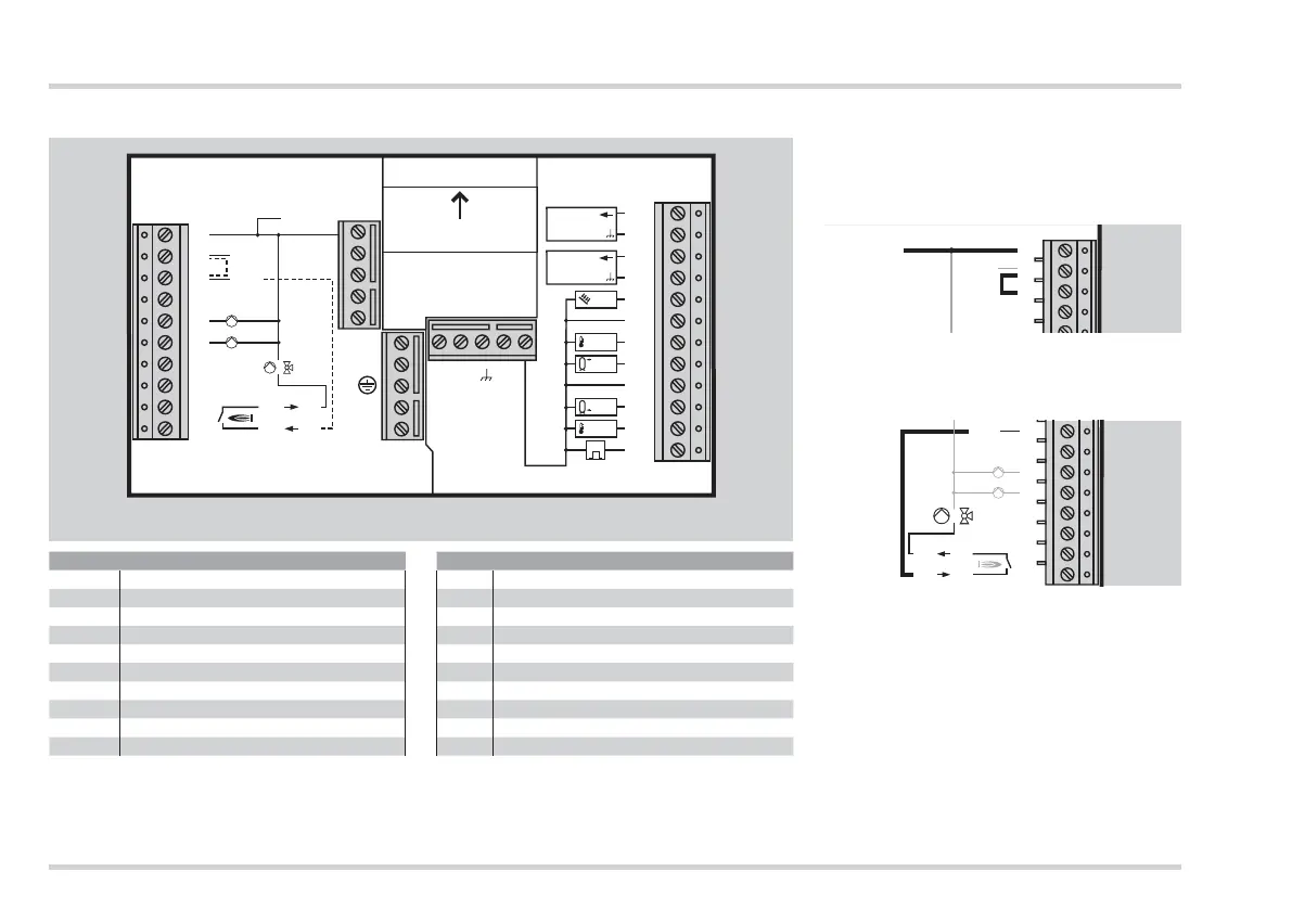
Technician - Electrical connections
Connection diagram controller in socket
N
GND
1
2
3
4
5
6
7
8
9
10
Sensor
230 V
11
12
13
14
15
16
17
18
19
20
21
22
A3
A2
A1 (n)
L1
N
T1
T2
L1’
/
Top
L1’
PWM
Pump A1
PWM
Pump A2
F2
2
F3
F4
F5
G
F1
5
~230 V, relay switching capacity 2(2)A,~250V SELV, safety extra low voltage
1 Neutral conductor mains
11 – 12
Speed of pump A1
2 Mains voltage heating controller L1
13 – 14
Speed of pump A2
3 Mains voltage for the outputs L1‘ 15 Sensor F1
5 Pump A2, variable-speed 16 Earth for sensor connections
6 Pump A1, variable-speed 17 Sensor F2
9 – 10 Relay, floating 18 Sensor F3
19 Earth for sensor connections
20 Sensor F4
21 Sensor F5
22 Pulse generator
ڀ
Provided no separate regulations for
protecting the relay apply, a bridge to
supply the relays for pump A1 and A2
must be connected between terminals
2 and 3.
1
2
3
L1
N
ڀ
A bridge must be connected terminals
3 and 10 if a connected actuator is
operated via the floating relay.
3
4
5
6
7
8
9
10
A3
A2
A1 (n)
T1
T2
L1’
/
L1’
ڀ
Use fixed cables or flexible cables
with wire end sleeves for connections
(230V). Connection to the CAN bus is
not possible.
ڀ
Collector sensor (F1): Use only KLF 1000,
see page 48 (Accessories).
ڀ Connect only sensors necessary for the
installation.
Bekijk gratis de handleiding van Daikin DSR1, stel vragen en lees de antwoorden op veelvoorkomende problemen, of gebruik onze assistent om sneller informatie in de handleiding te vinden of uitleg te krijgen over specifieke functies.
Productinformatie
| Merk | Daikin |
| Model | DSR1 |
| Categorie | Niet gecategoriseerd |
| Taal | Nederlands |
| Grootte | 4563 MB |


