Handleiding
Je bekijkt pagina 31 van 48
14 Piping installation
Installation and operation manual
31
BS4~12A14AJV1B9
VRV 5 branch selector unit
4P797565-1 – 2024.11
14.1.1 Piping installation limitation
In case of models BS6A, and BS8A, BS10A and BS12A: at least
one of the first four ports of the BS unit MUST be connected. In case
none of the first four ports are connected, the 7-segment display will
show ' '.
ABCDEFGH
0× 1× 2× 3× 4×
Model Branch pipe port
L K J I H G F E D C B A
BS6A free use ≥1 port MUST be
connected
BS8A free use
BS10A free use
BS12A free use
14.2 Preparing refrigerant piping
14.2.1 Refrigerant piping requirements
NOTICE
The piping and other pressure-containing parts shall be
suitable for refrigerant. Use phosphoric acid deoxidised
seamless copper for refrigerant piping.
▪ Foreign materials inside pipes (including oils for fabrication) must
be ≤30mg/10m.
14.2.2 Refrigerant piping material
Piping material
Phosphoric acid deoxidised seamless copper
Piping temper grade and thickness
Outer diameter
(Ø)
Temper grade Thickness (t)
(a)
6.4mm (1/4")
9.5mm (3/8")
12.7mm (1/2")
Annealed (O) ≥0.80mm
t
Ø
15.9mm (5/8") Annealed (O) ≥0.99mm
19.1mm (3/4")
22.2mm (7/8")
Half hard (1/2H) ≥0.80mm
28.6mm (11/8") Half hard (1/2H) ≥0.99mm
(a)
Depending on the applicable legislation and the maximum
working pressure of the unit (as indicated on the unit nameplate),
larger piping thickness might be required.
14.2.3 Refrigerant piping insulation
▪ Use polyethylene foam as insulation material:
▪ with a heat transfer rate between 0.041 and 0.052W/mK (0.035
and 0.045kcal/mh°C)
▪ with a heat resistance of at least 120°C
▪ Insulation thickness:
Ambient
temperature
Humidity Minimum thickness
≤30°C 75% to 80% RH 15mm
>30°C ≥80% RH 20mm
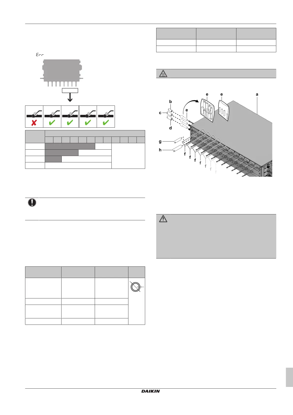
14.3 Connecting the refrigerant piping
DANGER: RISK OF BURNING/SCALDING
14.3.1 To connect the refrigerant piping
e
e
b
a
d
c
g
h
e
f
f
f
f
f
f
f
a BS unit
b Liquid pipe (field supply)
c HP/LP gas pipe (field supply)
d Suction gas pipe (field supply)
e Reducing joints and insulation tubes (accessory)
f Indoor unit connection set
g Liquid pipe (field supply)
h Gas pipe (field supply)
WARNING
Bent header or branch pipes can lead to refrigerant
leakage. Possible consequence: asphyxiation,
suffocation and fire.
▪ NEVER bend the branch and header pipes sticking out
of the unit. They have to remain straight.
▪ ALWAYS support the branch and header pipes at a
distance of 1m from the unit.
Prerequisite: Mount the indoor, outdoor and BS units.
Prerequisite: Read the instructions in the outdoor unit's manual for
information on how to install piping between the outdoor unit and the
BS unit, selecting a refrigerant branch kit, and installing piping
between the refrigerant branch kit and the BS units.
Prerequisite: Read the instructions in the indoor unit's manual for
information on how to install piping between the indoor unit and the
BS unit.
Prerequisite: When connecting piping, respect the guidelines for
pipe bending and brazing.
Prerequisite: Remove the yellow paper from around the header
pipes to avoid fire during brazing.
1 Connect the header pipes to the appropriate field supply pipes.
The type of pipe is indicated on the removed yellow paper. Use
a reducing joint (accessory) if the field supply pipe size does not
match the header pipe size of the BS unit. The diameters of the
header pipes of the BS unit are:
▪ Liquid pipe: 15.9mm
▪ HP/LP gas pipe: 22.2mm
▪ Suction gas pipe: 22.2mm
2 If necessary, cut the branch pipes as indicated in the illustration
below. The diameters of the branch pipes of the BS unit are
indicated in the illustration.
Bekijk gratis de handleiding van Daikin BS8A14AJV1B9, stel vragen en lees de antwoorden op veelvoorkomende problemen, of gebruik onze assistent om sneller informatie in de handleiding te vinden of uitleg te krijgen over specifieke functies.
Productinformatie
| Merk | Daikin |
| Model | BS8A14AJV1B9 |
| Categorie | Airco |
| Taal | Nederlands |
| Grootte | 8827 MB |


