D-Link DPS-PWR740AC handleiding
Handleiding
Je bekijkt pagina 32 van 69
DMS-3130 Series Layer 3 Stackable Managed Switch Hardware Installation Guide
32
Firstly, remove the AC power cord from the AC power port of the Switch. Then, insert one end of the 14-pin DC power
cable into the port on the switch and the other end into the RPS. Next, use a standard AC power cable to connect the
RPS to the main AC power source. A green LED on the front of the RPS will glow to indicate a successful connection.
Reconnect the AC power cord to the AC power port of the Switch. The RPS LED indicator on the front panel of the
Switch will indicate that an RPS is now present and in operation. No software configuration is required.
NOTE: See the DPS-500A documentation for more information.
CAUTION: This equipment is to be connected only to PoE networks without routing to the outside
plant.
Installing the RPS into a Rack-mount Chassis
DPS-800 Rack-mount Chassis
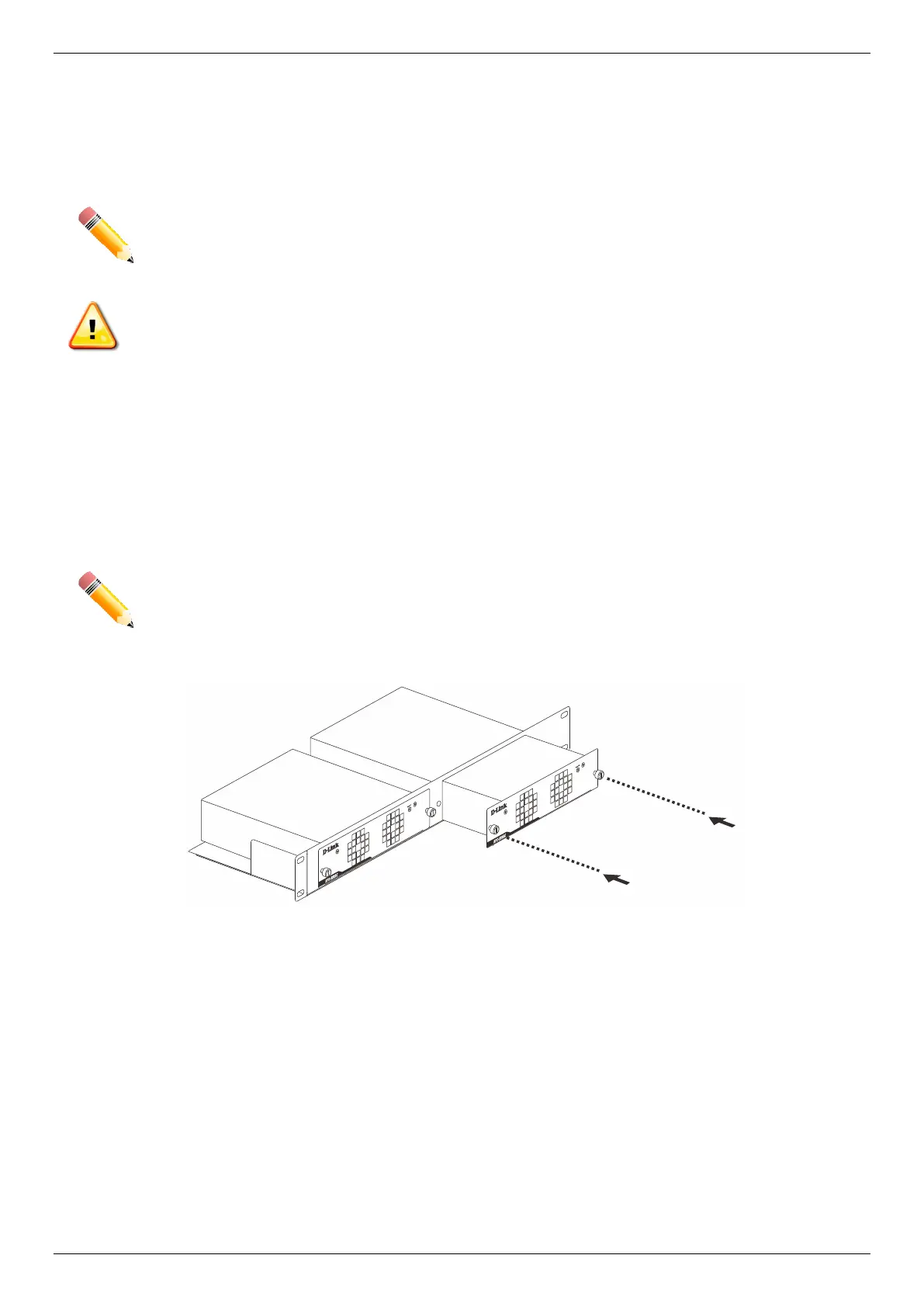
The DPS-800 is a standard-size (1 standard unit in height) rack-mountable unit designed to hold up to two RPS units.
NOTE: This rack-mounted chassis supports the following RPS units: DPS-500A.
The following diagram illustrates how a DPS-500A is installed into a DPS-800.
Figure 3–15 Install the DPS-500A into the DPS-800
The DPS-800 can be mounted into a standard 19" rack, as shown below.
Bekijk gratis de handleiding van D-Link DPS-PWR740AC, stel vragen en lees de antwoorden op veelvoorkomende problemen, of gebruik onze assistent om sneller informatie in de handleiding te vinden of uitleg te krijgen over specifieke functies.
Productinformatie
| Merk | D-Link |
| Model | DPS-PWR740AC |
| Categorie | Niet gecategoriseerd |
| Taal | Nederlands |
| Grootte | 10019 MB |


