D-Link DPS-PWR740AC handleiding
Handleiding
Je bekijkt pagina 18 van 69
DMS-3130 Series Layer 3 Stackable Managed Switch Hardware Installation Guide
18
LED
Description
green when a 25 Gbps port is active or blink amber when a 10 Gbps port is active.
The LED will be off when there is no link or activity.
Stack ID
This 7-segment LED can display numbers from 1 to 9 and the following letters H,
h, E, and G. The stacking ID (1 to 9) can be assigned manually by the user or
automatically by the system.
The letter ‘H’ will be displayed if this switch is the master switch in the stack.
The letter ‘h’ will be displayed if this switch is the backup master switch in the
stack.
The letter ‘E’ will be displayed if there was an error in the system’s self-test.
The letter ‘G’ will be displayed when the Safeguard engine entered the
exhausted mode.
Please refer to the “LED Indicators” section in the Appendix A - Technical Specifications for more LED information.
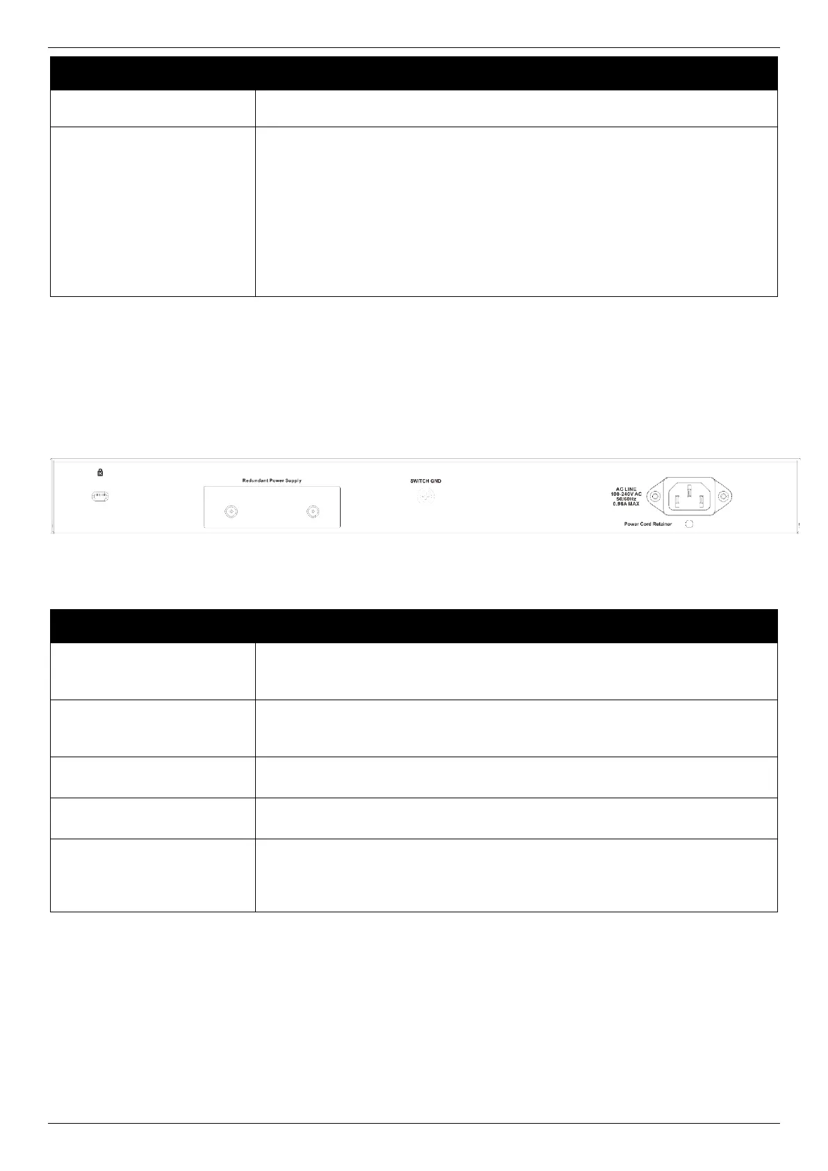
Rear Panel Components
The rear panel of this switch features a security lock, a GND, an AC power connector, a power cord retainer hole, and
an outlet for an external redundant power supply.
Figure 2-3 Rear panel view of the DMS-3130-30TS
Components on the rear panel of this switch
Component
Description
Security Lock
Provide a Kensington-compatible security lock to connect to a secure immovable
device. Insert the lock into the notch and turn the key to secure the lock. The lock-
and-cable apparatus should be purchased separately.
Switch GND
Use an electrical grounding wire and connect one end of the wire to the Switch
GND and the other end of the wire to an electrical grounding point most found on
the Switch mounting rack itself.
AC Power Connector
The AC power cord with a three-pronged AC power connector can be plugged into
this receptacle to supply the Switch with 100-240 VAC power at 50-60 Hz.
Power Cord Retainer Hole
The power cord retainer hole is used to insert the power cord retainer to secure
the AC power cord.
Redundant Power Supply
An optional external RPS can be plugged into the RPS port found on the rear
panel. When the internal power fails, this optional external RPS will supply power
to the Switch immediately and automatically. The metal cover plate should be
mounted if there’s no RPS to be plugged.
Side Panel Components
The side panels of this switch contain heat vents, fans, and rack-mounting screw holes. The heat vents are used to
dissipate internal heat and facilitate internal air circulation. Do not block these openings. Leave at least 4 inches of
space at the sides of the Switch for proper ventilation. Without proper heat dissipation and air circulation, system
components might overheat and lead to system failure or even severe damage.
Bekijk gratis de handleiding van D-Link DPS-PWR740AC, stel vragen en lees de antwoorden op veelvoorkomende problemen, of gebruik onze assistent om sneller informatie in de handleiding te vinden of uitleg te krijgen over specifieke functies.
Productinformatie
| Merk | D-Link |
| Model | DPS-PWR740AC |
| Categorie | Niet gecategoriseerd |
| Taal | Nederlands |
| Grootte | 10019 MB |


