D-Link DIS-100G-8SW handleiding
Handleiding
Je bekijkt pagina 3 van 4
3
DANGER:
Never attempt to view optical connectors
that might be emitting laser energy.
Do not power up the laser product without
connecting the laser to the optical fiber and
putting the cover in position, as laser
outputs will emit infrared laser light at this
point.
Power Connecting
The switch can be powered from two power supply (input
range 12V – 58V). Insert the positive and negative wires
(AW G 14-26) into V+ and V- contact on the terminal block
and tighten the wire-clamp screws to prevent the wires from
being loosened.
NOTE:
1. The DC power should be connected to a
well-fused power supply.
2. Input power should be within the range
of 54~58VDC for PoE+ compliant, or
48-58VDC for PoE compliant.
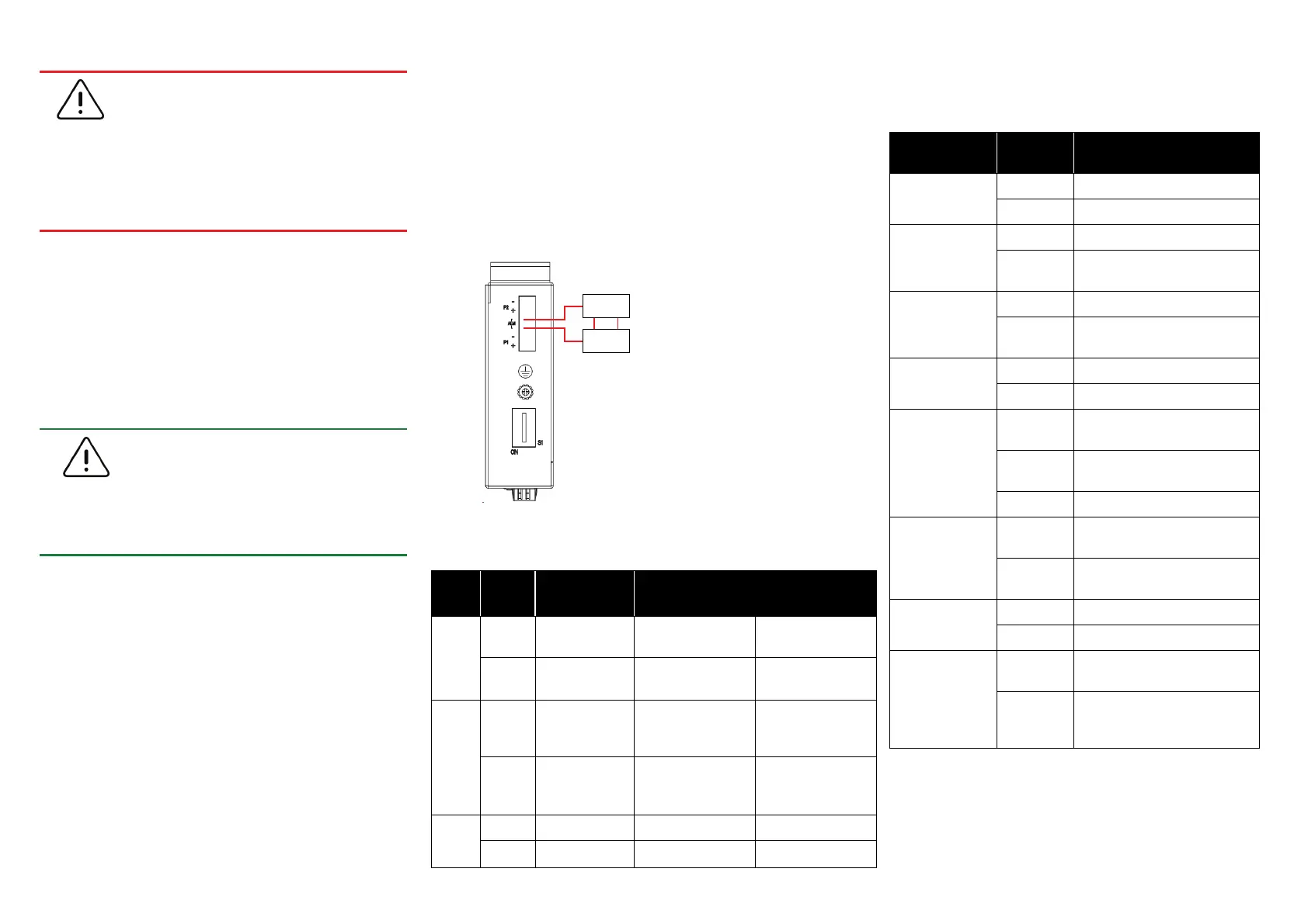
Alarm Relay Connecting (for Non-PoE Models)
The alarm relay output contacts are in the middle of the DC
terminal block connector shown as the figure below.
By inserting the wires and set the DIP switch of the
respective Port Alarm to “ON”, the relay output alarm will
detect any port failures, and form a short circuit.
The alarm relay out is “Normal Open”.
Alarm
system
Extra power
system
Maximum 1A / DC 24V
DIP Switch Setting
LED STATUS INDICATIONS
LED Name Indicator/
color
Condition
PoE
On Green PoE is working.
Off PoE is not working
P1
On Green P1 power line has power
Off P1 power line disconnect or
does not have supply power
P2
On Green P2 power line has power
Off P2 power line disconnect or
does not have supply power
ALM
On Red Power failure alarm occurs
Off No power failure alarm
Copper 1 to N
port Link/Act
On Green Ethernet link up but no traffic is
detected
Blinking
Green
Ethernet link up and there is
traffic detected
Off Ethernet link down
Copper 1 to N
port Speed
On Yellow A 1000Mbps connection is
detected
Off No link, a 10Mbps or 100
Mbps connection is detected
SFP 1 to N port
(N=0,1,2)
Link/Act
On Green Ethernet link up
Off Ethernet link down
SFP 1 to N port
(N=0,1,2) Speed
On Yellow SFP port speed 1000Mbps
connection is detected.
Off No link or a SFP port speed
100Mbps connection is
detected
Pin
No#
Status
DIS-100G-5W
DIS-100G-5SW
DIS-100G-5PSW
DIS-100G-8W
DIS-100G-8SW
Pin 1
ON
To enable the
power alarm.
To enable Broadcast
storm rate limit.
To enable Broadcast
storm rate limit.
OFF
To disable the
power alarm.
To disable Broadcast
storm rate limit
To disable Broadcast
storm rate limit
Pin 2
ON
To enable
Broadcast storm
rate limit
NOT USED
To enable Broadcast
storm rate limit.
OFF
To disable
Broadcast storm
rate limit
NOT USED
To disable Broadcast
storm rate limit
Pin 3-6
ON NOT USED NOT USED NOT USED
OFF NOT USED NOT USED NOT USED
Bekijk gratis de handleiding van D-Link DIS-100G-8SW, stel vragen en lees de antwoorden op veelvoorkomende problemen, of gebruik onze assistent om sneller informatie in de handleiding te vinden of uitleg te krijgen over specifieke functies.
Productinformatie
| Merk | D-Link |
| Model | DIS-100G-8SW |
| Categorie | Niet gecategoriseerd |
| Taal | Nederlands |
| Grootte | 813 MB |


