CYP IP-CS9000 handleiding
Handleiding
Je bekijkt pagina 9 van 72
4
6. OPERATION CONTROLS AND FUNCTIONS
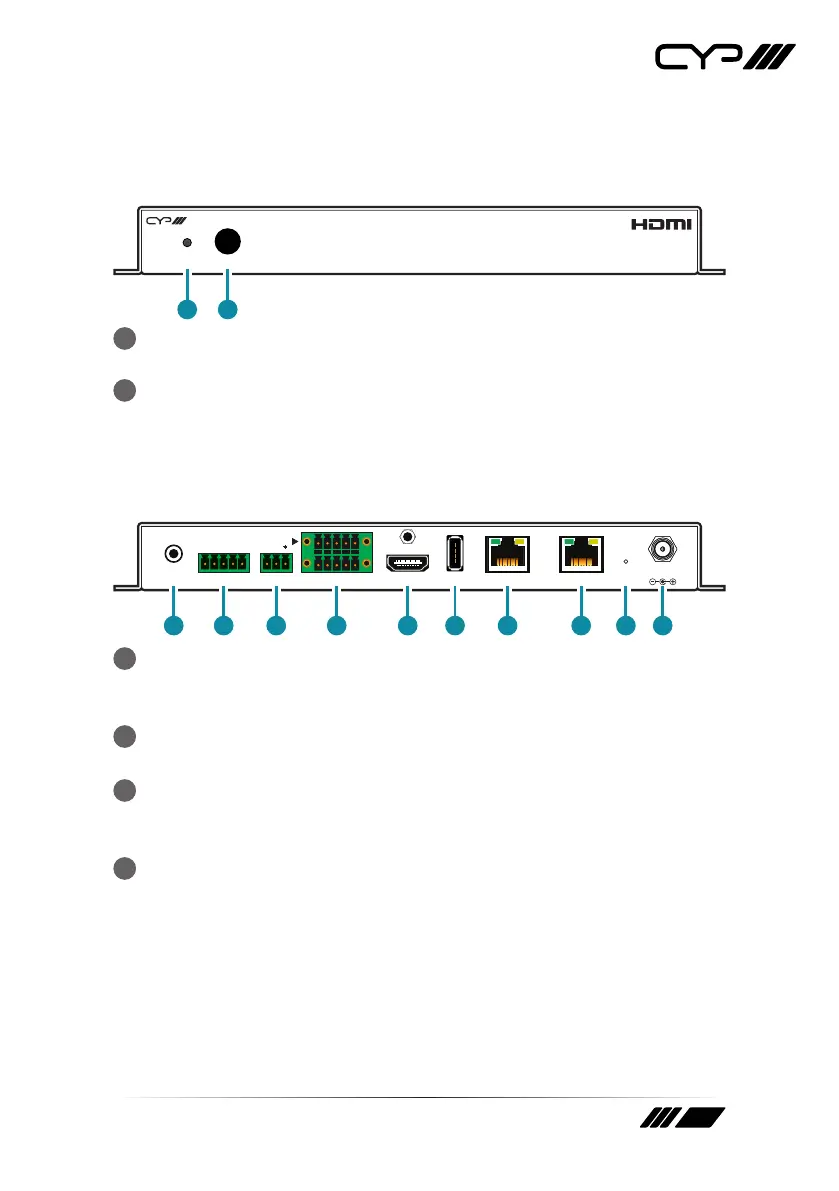
6.1 Front Panel
IP-CS9000
POWER
IR
1 2
1
POWER LED: This LED will illuminate to indicate the unit is on and
receiving power.
2
IR Window: Accepts IR signals from the included IR remote for control
of this unit only.
6.2 Rear Panel
LAN 1(POE) LAN 2USBHDMI OUTRS-232CONTROLIR EXT
DC 5V
TRIGGER IN
TX RX
1 2 3 4 5 6 7 8 109
1
IR EXT Port: Connect to the provided IR Extender to extend the IR
control range of the unit. Ensure that the remote being used is within
direct line-of-sight of the IR Extender.
2
CONTROL 5-pin Terminal Block: Connect to a serial controllable
device for the transmission of RS-232 signals.
3
RS-232 3-pin Terminal Block: Connect to a PC, laptop or other serial
control device with a 3-pin adapter cable to control the unit via RS-
232.
4
TRIGGER IN 10-pin Terminal Block: Connect to 3
rd
party trigger or
any device with trigger switch functionality such as window security
alarms, motion detectors, door switches, etc. Each of the 8 trigger
inputs will activate the associated macro (1~8) when triggered.
Note: A minimum of 5V DC is required to activate each trigger.
Bekijk gratis de handleiding van CYP IP-CS9000, stel vragen en lees de antwoorden op veelvoorkomende problemen, of gebruik onze assistent om sneller informatie in de handleiding te vinden of uitleg te krijgen over specifieke functies.
Productinformatie
| Merk | CYP |
| Model | IP-CS9000 |
| Categorie | Niet gecategoriseerd |
| Taal | Nederlands |
| Grootte | 5938 MB |


