Curtis enGage VI handleiding
Handleiding
Je bekijkt pagina 12 van 24
12Curtis Instruments enGage
®
VI Manual
2.2 SWITCH INPUTS
The switch inputs may be Active-low (switched to B–) or Active-high (switched to B+). The input
specications are given in Table 11 below.
Keyswitch Input
The keyswitch input meets the same input specications as the switch inputs (see Table 11). This input
is active only when switched to B+.
Backlight Dimmer Control Input
Backlighting is adjustable via the front panel buttons & menu or an optional 10k potentiometer can
be connected to J2-8 & B– to externally control the backlight. If an external pot is used for backlight
adjustment, backlight adjustment via the menu is disabled.
Sender Inputs
Each sender input can be programmed for either a resistive or voltage based sender. The sender must
be referenced to the system ground (B–) connected to the unit. Input requirements and specications
are given in Table 12 below.
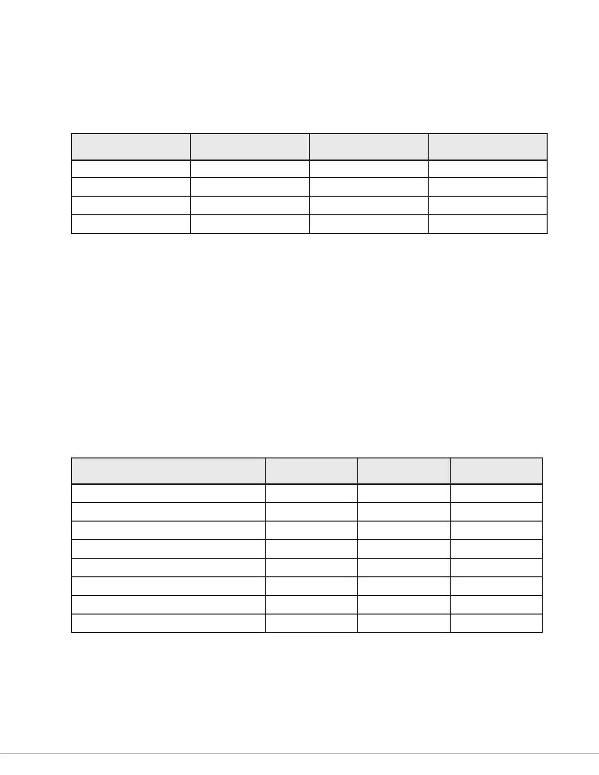
Table 11 Switch Input Specications
Parameter Min. Max. Units
Input Range 0 180 Volts
Active-High Threshold 8.0 — Volts
Active-Low Threshold — 1.0 Volts
Input Impedance 741 k 819 k Ohms
Table 12 Sender Input Specications
Parameter Min. Max. Units
Voltage Input Range 0 180 V DC
Voltage Measurement Range 0 10 V DC
Voltage Resolution — 10 mV
Voltage Measurement Error — +/– (1% + 40 mV)
Resistance Measurement Range 0 10 k Ohms
Resistance Resolution (0–1200 Ω) 0.2 5 Ohms
Resistance Resolution (1.2k–10k Ω) 5 35 Ohms
Resistance Measurement Error — +/– (3% + 2 Ω)
Bekijk gratis de handleiding van Curtis enGage VI, stel vragen en lees de antwoorden op veelvoorkomende problemen, of gebruik onze assistent om sneller informatie in de handleiding te vinden of uitleg te krijgen over specifieke functies.
Productinformatie
| Merk | Curtis |
| Model | enGage VI |
| Categorie | Niet gecategoriseerd |
| Taal | Nederlands |
| Grootte | 2124 MB |


