Curtis 1352 handleiding
Handleiding
Je bekijkt pagina 9 van 40
2 — INSTALLATION AND WIRING
pg. 5
Return to TOC Curtis 1352 eXm Manual, June 2021
You will need to take steps during the design and development of your end product to ensure that its
EMC performance complies with applicable regulations; suggestions are presented in Appendix A.
e 1352 eXm contains ESD-sensitive components. Use appropriate precautions in connecting,
disconnecting, and handling the module. See installation suggestions in Appendix A for protecting
the module from ESD damage.
Working on electrical systems is potentially dangerous. You should protect yourself against
uncontrolled operation, high current arcs, and outgassing from lead acid batteries:
UNCONTROLLED OPERATION — Some conditions could cause the motor to run out of control.
Disconnect the motor or jack up the vehicle and get the drive wheels off the ground before
attempting any work on the motor control circuitry.
HIGH CURRENT ARCS — Batteries can supply very high power, and arcing can occur if they
are short circuited. Always open the battery circuit before working on the motor control circuit.
Wear safety glasses, and use properly insulated tools to prevent shorts.
LEAD ACID BATTERIES — Charging or discharging generates hydrogen gas, which can build
up in and around the batteries. Follow the battery manufacturer’s safety recommendations.
Wear safety glasses.
CAUTION
CONNECTIONS
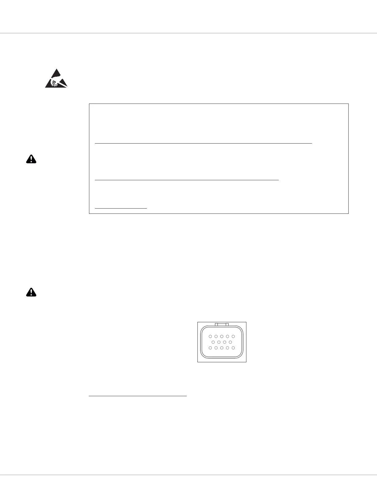
All connections are made through the 14-pin AMPSEAL connector. e mating plug housing is
AMP p/n 776273-1, and the gold-plated socket terminals are AMP p/n 770520-3 (Strip form) and
770854-3 (loose piece). e connector will accept 20 to 16 AWG wire with a 1.7 to 2.7mm diameter
thin-wall insulation.
Note that the eXm pins are not sealed until the mating connector is fully engaged and locked.
e cable harness connector has a silicone rubber seal that is an integral part of the module’s sealing.
e 14 individual pins are characterized in Table 1.
51
1410
6 9
Wiring recommendations
Power and ground (Pins 1–3)
e B+ and B– cables should be run close to each other between the module and the battery. For
best noise immunity the cables should not run across the center section of the module. To prevent
overheating these pins, the wire gauge must be sucient to carry the continuous and maximum
loads that will be seen at each pin.
CAUTION
Bekijk gratis de handleiding van Curtis 1352, stel vragen en lees de antwoorden op veelvoorkomende problemen, of gebruik onze assistent om sneller informatie in de handleiding te vinden of uitleg te krijgen over specifieke functies.
Productinformatie
| Merk | Curtis |
| Model | 1352 |
| Categorie | Niet gecategoriseerd |
| Taal | Nederlands |
| Grootte | 5176 MB |


