Curtis 1352 handleiding
Handleiding
Je bekijkt pagina 14 van 40
2 — INSTALLATION AND WIRING
Curtis 1352 eXm Manual, June 2021
Return to TOC
pg. 10
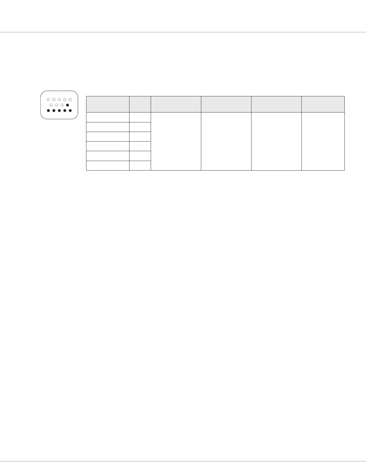
Digital outputs
e six digital I/O lines can also be used as outputs. ey can be either digital (on/o) or Pulse Width
Modulated (PWM) outputs. Each driver is active low, meaning the output will pull low (to B–) when
On. e PWM is at a xed frequency (16 kHz), and can vary duty cycle from 0 to 100%.
DIGITAL OUTPUT SPECIFICATIONS
SIGNAL NAME PIN
PWM &
FREQUENCY
OUTPUT
CURRENT*
PROTECTED
VOLTAGE RANGE
ESD
TOLERANCE
Input/Output 1 11 All models:
0–100% duty
cycle at 16 kHz
All models:
Sink 3 A
12–36V models:
–0.5 to 50 V
36–80V models:
–0.5 to 105 V
All models:
±8 kV (air
discharge)
Input/Output 2 12
Input/Output 3 13
Input/Output 4 14
Input/Output 5 9
Input/Output 6 10
*Tolerance ±5%.
51
1410
6 9
e drivers can be set for Constant Current, Constant Voltage, or Direct PWM control mode.
In Constant Current mode, the driver command of 0 to 100% is interpreted as a
current from 0 to Max Output setting (up to 3 amps). Internal current shunts are
measured and fed back to a closed loop PI controller to provide a steady current
over changing loads and supply voltages.
In Constant Voltage mode, the driver command of 0 to 100% is interpreted as a
voltage from 0 to Max Output (up to 80 volts). e battery voltage is constantly
monitored and fed back to a closed loop PI controller to provide a steady voltage,
compensating for battery droop and discharge. If the command is higher than the
driver can output, the PWM will max out at 100%.
In Direct PWM mode, the driver command of 0 to 100% is directly output on
the driver.
Each driver is monitored and will detect a short in the load, a failed internal driver FET, and/or an
open in the load wiring. At near 0% and 100% PWM, it is not possible to discern each fault and some
faults will not be detected.
If the driver outputs are connected to inductive loads, the coil should have a return line to the B+ pin
of the eXm. is connection provides a path for the internal freewheel diodes to clamp the turn-o
spike. Failure to make this connection with inductive loads can cause permanent damage to the eXm
module as well as propagate failures of other electronics in the system due to the high voltage spike
caused when an inductive load turns o without a freewheel path.
Bekijk gratis de handleiding van Curtis 1352, stel vragen en lees de antwoorden op veelvoorkomende problemen, of gebruik onze assistent om sneller informatie in de handleiding te vinden of uitleg te krijgen over specifieke functies.
Productinformatie
| Merk | Curtis |
| Model | 1352 |
| Categorie | Niet gecategoriseerd |
| Taal | Nederlands |
| Grootte | 5176 MB |


