Curtis 1268 handleiding
Handleiding
Je bekijkt pagina 13 van 66
Curtis 1268 Manual, Rev. D 7
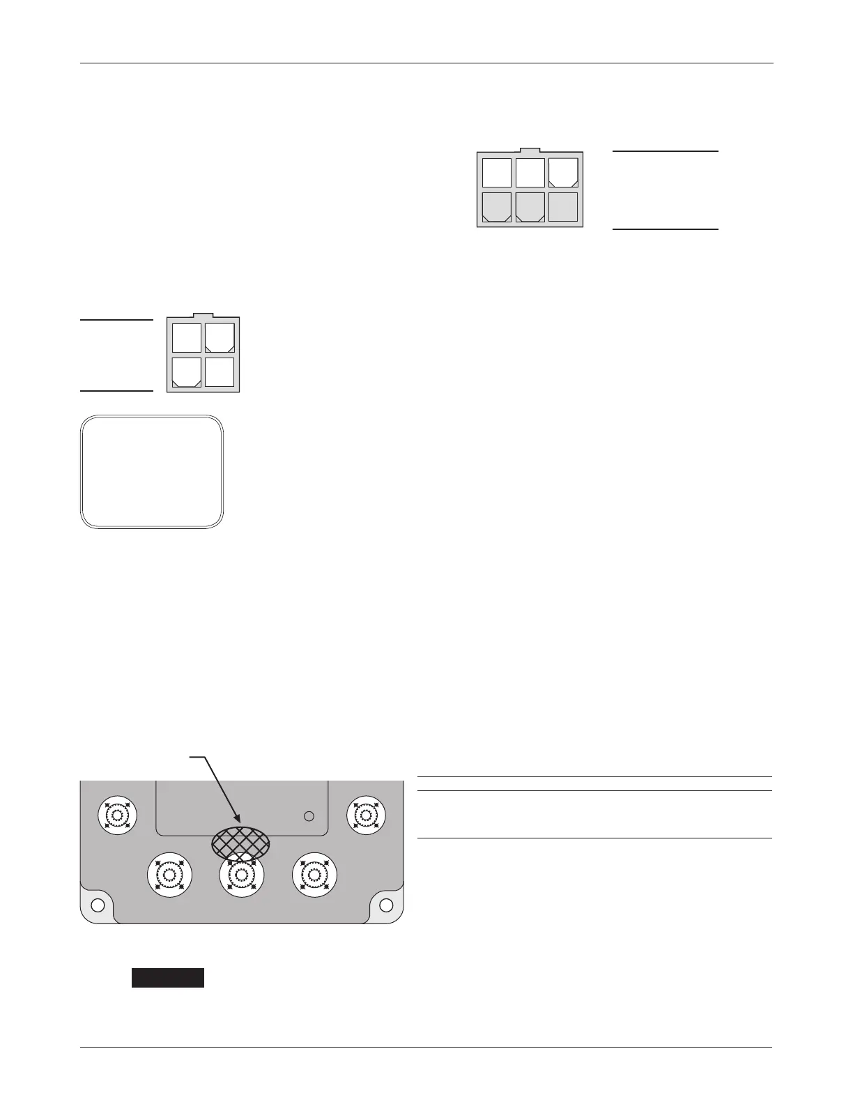
F1
B- B+M-
F2
STATUS
LED
CABLE-FREE ZONE
A 6-pin low power Molex connector is provided for the interface with the Hall
speed sensor. The mating connector is a Molex Mini-Fit Jr. p/n 39-01-2065
using type 5556 terminals.
J2-1,2,3 (not used)
J2-4 ground
J2-5 input
J2-6 +15V
Power cables must not be routed over the indicated area. Otherwise they
may interfere with the proper operation of sensitive electromagnetic compo
-
nents located underneath.
The +15V supply should only be used with the speed sensor and not to power
any other external systems.
A 4-pin low power connector is provided for an optional programmer. A com-
plete handheld programmer kit, including the appropriate connecting cable
with mating connector, can be ordered from Curtis:
p/n 168961101 for the User Programmer (model 1311-1101)
p/n 168962101 for the OEM Programmer (model 1311-4401).
If a handheld programmer is already available (such as the now discontinued
1307) but has an incompatible cable, the appropriate connecting cable can be
ordered as a separate part: p/n 16185.
If a 1314 PC programming station is used, the 1309 interface box and cable
connect the computer to the controller:
p/n 117465704 1314-1101, 1314 PC Programming Station (User) CD-ROM
p/n 117465707 1314-4401, 1314 PC Programming Station (OEM) CD-ROM
p/n 16994001 1309 Interface Box
p/n 16185 Molex cable for 1309 Interface Box.
High Current Connections
Five tin-plated solid aluminum bus bars are provided for the high current con-
nections to the battery
(B+ and B-), the motor armature (M-), and the motor
field (F1 and F2). These bus bars incorporate threaded mounting studs designed
to accept mounting bolts. This simplifies the assembly and reduces the mount
-
ing hardware necessary for the power connections.
SIZE MAX DEPTH QTY MAX TORQUE
Field studs M6 × 1 5/8" 2 16.3 N·m (12 ft-lbs)
Power studs M8 × 1.25 3/4" 3 20.0 N·m (15 ft-lbs)
Exceeding these specifications could damage the bus
bars’ internal threads, resulting in loose connections.
We recommend maximum possible thread engagement:
always exceeding three threads.
2 — INSTALLATION & WIRING: Controller
456
123
34
12
J3
J2
J3-1 Rx Data
J3-2 B-
J3-3 Tx Data
J3-4 +15V
☞
C A U T I O N
note: The 1311 hand-
held programmer has
been superseded; if you
are using a more recent
model, please refer to its
documentation.
Bekijk gratis de handleiding van Curtis 1268, stel vragen en lees de antwoorden op veelvoorkomende problemen, of gebruik onze assistent om sneller informatie in de handleiding te vinden of uitleg te krijgen over specifieke functies.
Productinformatie
| Merk | Curtis |
| Model | 1268 |
| Categorie | Niet gecategoriseerd |
| Taal | Nederlands |
| Grootte | 7778 MB |


