Curtis 1229 handleiding
Handleiding
Je bekijkt pagina 42 van 143
3 — I/O MAPPING
1229 Manual - OS 1.8 RevA - May 2021
Return to TOC
pg. 36
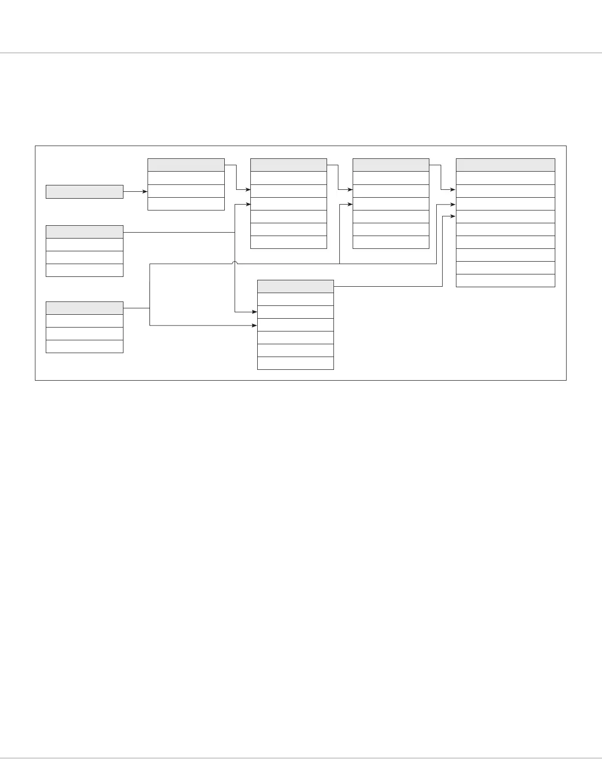
Example 8: Conguring an actuator
In this example, a vehicle is congured to operate a bidirectional actuator using Driver 3 & 4 as an
H-bridge, from pushbuttons on Switch 2 (“Li” = Fwd) and Switch 3 (“Lower” = Rev). If both buttons
are pushed simultaneously, the actuator does not move. “Li” is not allowed if BDI is below 15%.
Function 86-Driver 3/4 Actuator is used here to make an H-bridge for bidirectional motor control
using Drivers 3 & 4. Setting the function’s Enable parameter to On automatically disables functions
82-Driver 3 and 83-Driver 4. The actuator function also has programmable Accel/Decel, Stop
Current (stall detect), and Battery Voltage Compensation parameters. e signal mapped to the
Input parameter species the duty cycle, the signal mapped to Rev Input species the direction, and
the signal mapped to Enable Input enables the H-bridge.
In this example, the duty cycle is generated using 43-Logic Gate 3 to “or” Switch 3 (Lower), with
another signal generated from 41-Logic Gate 1, which says Switch 2 (Li) is pressed and BDI is >15%.
e Reverse Input signal is taken directly from Switch 3.
e Enable Input is generated using 42-Logic Gate 2 to “xor” Switches 2 & 3. is will result in 100%
(On) if one button is pressed, and 0% (O) if both buttons or neither button is pressed.
is example provides a good opportunity to discuss the movement of signals through the I/O map.
e controller rmware scans the entire map every 8 ms, in the order that the functions are numbered
(i.e., it calculates function 0, then function 1, then function 2, etc.). is means that signal chains that
always propagate forward (from lower numbered functions to higher numbered functions) will be
completely calculated every 8 ms. Every time a signal propagates backward (from a higher number
to a lower number) there is an 8 ms delay in that signal reaching its destination. For this reason, the
I/O map functions are ordered such that inputs are rst, followed by conditioning functions, and
outputs last. (Note: is does not apply to vehicle status functions, those numbered 100 or above,
which are scanned at a lower rate because they don’t change this quickly.)
In example 8, logic gates 41 & 43 are chained in an order that allows the signal to propagate forward.
If the two logic gates (and their parameter settings) were swapped, the backwards propagation would
cause an 8 ms delay. In this example, that would not be a problem; but in an application chaining all
ten logic gates, backwards propagation could create a delay as long as 80 ms.
2-Switch 2
On Delay = 0.1 s
Off Delay = 0.1 s
Normally Closed = Off
3-Switch 3
On Delay = 0.1 s
Off Delay = 0.1 s
Normally Closed = Off
107-BDI
17-Threshold 4
Input = 107
On Threshold = 15%
Off Threshold = 14%
41-Logic Gate 1
AND/OR/XOR = 1
Input 1 = 17
Input 2 = 2
Input 1- = Off
Input 2- = Off
Output- = Off
43-Logic Gate 3
AND/OR/XOR = 2
Input 1 = 41
Input 2 = 3
Input 1- = Off
Input 2- = Off
Output- = Off
86-Driver 3/4 Actuator
Enabled = On
Input = 43
Rev Input = 3
Enable Input = 42
Accel = 1.0 s
Decel = 1.0 s
Stop Current = 10 A
Stop Current Time = 1.0 s
Battery Voltage Comp = Off
42-Logic Gate 2
AND/OR/XOR = 3
Input 1 = 2
Input 2 = 3
Input 1- = Off
Input 2- = Off
Output- = Off
Bekijk gratis de handleiding van Curtis 1229, stel vragen en lees de antwoorden op veelvoorkomende problemen, of gebruik onze assistent om sneller informatie in de handleiding te vinden of uitleg te krijgen over specifieke functies.
Productinformatie
| Merk | Curtis |
| Model | 1229 |
| Categorie | Niet gecategoriseerd |
| Taal | Nederlands |
| Grootte | 19864 MB |


