Curtis 1229 handleiding
Handleiding
Je bekijkt pagina 35 van 143
3 — I/O MAPPING
pg. 29
Return to TOC 1229 Manual - OS 1.8 RevA - May 2021
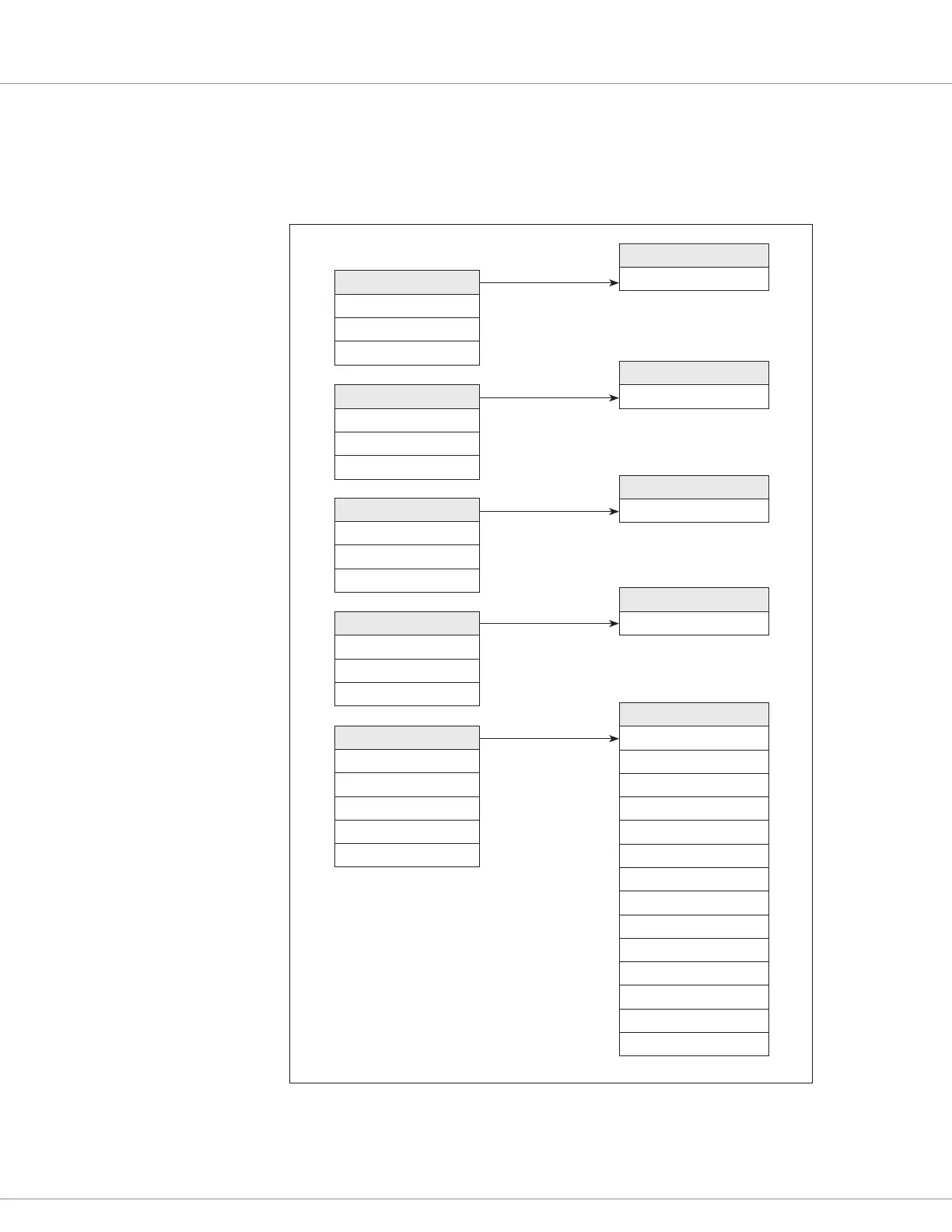
Example 1: Basic mapping of digital and analog inputs to controller functions
In this example, a vehicle is congured as shown in Figure 9, with switches on Switch 1 (pin J1-19)
for forward, Switch 2 (pin J1-10) for reverse, Switch 3 (pin J1-3) for speed mode, and Switch 4 (pin
J1-11) for interlock, and a potentiometer on Pot 1 (pin J1-13) for throttle.
Signal #1
Signal #2
Signal #3
Signal #4
Signal #11
1-Switch 1
On Delay = 0.1 s
Off Delay = 0.1 s
Normally Closed = Off
2-Switch 2
On Delay = 0.1 s
Off Delay = 0.1 s
Normally Closed = Off
3-Switch 3
On Delay = 0.1 s
Off Delay = 0.1 s
Normally Closed = Off
4-Switch 4
On Delay = 0.1 s
Off Delay = 0.1 s
Normally Closed = Off
11-Pot 1
Max = 4.0 V
Min = 1.0 V
Fault High = 4.5 V
Fault Low = 0.5 V
Fault Action = 2
92-Forward
Input = 1 (Switch 1)
93-Reverse
Input = 2 (Switch 2)
94-Speed Mode
Input = 3 (Switch 3)
97-Interlock
Input = 4 (Switch 4)
91-Throttle
Input = 11 (Pot 1)
Enable Input = 100
Fwd Deadband = 5%
Fwd Max = 97%
Fwd 0% Offset = 3%
Fwd 50% Map = 65%
Rev Deadband = 5%
Rev Max = 97%
Rev 0% Offset = 3%
Rev 50% Map = 65%
Throttle Filter = 100 Hz
HPD Type = 1
SRO Type = 1
HPD Threshold = 3%
Mapping is the process of setting a function’s input parameter to the number of the signal you want to
map. For example, setting “92-Forward Input = 1” maps Switch 1 into the Forward function; setting
“93-Reverse Input = 2” maps Switch 2 into the Reverse function; etc.
Bekijk gratis de handleiding van Curtis 1229, stel vragen en lees de antwoorden op veelvoorkomende problemen, of gebruik onze assistent om sneller informatie in de handleiding te vinden of uitleg te krijgen over specifieke functies.
Productinformatie
| Merk | Curtis |
| Model | 1229 |
| Categorie | Niet gecategoriseerd |
| Taal | Nederlands |
| Grootte | 19864 MB |


