Curtis 1226BL handleiding
Handleiding
Je bekijkt pagina 43 van 124
3 — PROGRAMMABLE PARAMETERS
pg. 35
Return to TOC Curtis Model 1226BL – July 2024
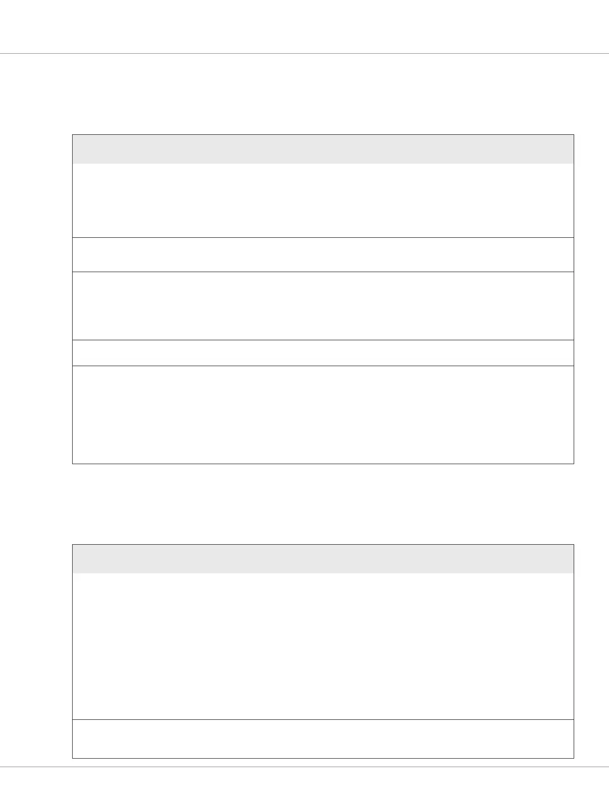
INTERLOCK MENU
e following table describes the interlock parameters.
INTERLOCK MENU
PARAMETER
CAN INDEX
VALUES
DEFAULT
RAW VALUES
DATA SIZE DESCRIPTION
Interlock Type
[PCF]
0x34B401
0–2
0
0–2
16-bit
Species the input used as the interlock switch:
0 = Interlock input
1 = Keyswitch
2 = Redundant Interlock Switch
Note: If Redundant Interlock Switch is specied, the Redundant
Interlock Switch submenu is displayed.
Interlock SRO Enable
0x34B901
Off/On
On
0–1
8-bit
Species whether the controller will generate an Interlock SRO
fault if the interlock switch is on before the keyswitch is turned
on. On indicates that the controller should generate the fault.
Interlock Brake Enable
0x34B501
Off/On
On
0–1
16-bit
Species whether the interlock braking function stops the
vehicle when the interlock signal is turned off:
On = The controller uses regen braking to stop the vehicle.
Off = The controller turns the motor off and lets the vehicle roll
freely. This option is typically used only when the vehicle
includes a user controlled mechanical or hydraulic brake.
Interlock Brake Decel Rate
0x34B601
0.1–8.0s
1.0s
50–4000
16-bit
Species the rate at which the vehicle decelerates when the
interlock is released. Larger values represent slower response times.
Interlock Brake Timeout
0x34B701
0.1–8.0s
2.0s
50–4000
16-bit
Species the maximum allowable duration of an interlock
braking event.
The timer starts when the interlock state changes to off. If the
time expires before the vehicle has stopped, the controller
engages the EM brake.
This timeout allows parallel usage of regen braking and the EM
brake to reduce stopping distance. If the timeout expires and
the motor is still moving, regen braking will continue to slow
vehicle motion in conjunction with the EM brake.
REDUNDANT INTERLOCK SWITCH MENU
PARAMETER
CAN INDEX
VALUES
DEFAULT
RAW VALUES
DATA SIZE DESCRIPTION
Switch Source
0x526F00
Enumerated
Digital 1
0–9
8-bit
Species the input used for the redundant interlock switch.
Values 1–9 correspond to the “typical functions” listed in
Table 1.
0 = CAN Switch (bit 12 of the CAN Switches object)
1 = Interlock
2 = EMR NC
3 = Charger Inhibit
4 = EMR NO
5 = Forward
6 = Reverse
7 = Mode
8 = Lift
9 = Digital 1
Switch Type
0x527000
Enumerated
NC
0–1
8-bit
Species whether the switch is NO or NC:
0 = NO
1 = NC
Redundant Interlock Switch Menu
e following parameters congure the redundant interlock input.
Bekijk gratis de handleiding van Curtis 1226BL, stel vragen en lees de antwoorden op veelvoorkomende problemen, of gebruik onze assistent om sneller informatie in de handleiding te vinden of uitleg te krijgen over specifieke functies.
Productinformatie
| Merk | Curtis |
| Model | 1226BL |
| Categorie | Niet gecategoriseerd |
| Taal | Nederlands |
| Grootte | 15971 MB |


